
Abstract
Aluminum BIW closures present significant dimensional challenges due to large springback and complex joining and hemming processes. To address these issues, a combined application of AutoForm Forming and AutoForm Assembly was developed to establish a full-process CAE workflow capable of accurately predicting closure dimensional behavior.
In the aluminum hood assembly of a NIO vehicle, CAE-based dimensional analysis and VAR technology were applied, achieving an 84% pass rate in the first-piece tryout loop for flush dimensions. In addition, 88% of simulated flush dimensions showed less than 0.5 mm deviation from real assembly results. These results significantly reduced tryout time for both single panels and the final hood assembly.
Introduction
With increasing competition in China’s EV market, OEMs are striving to strengthen their competitive position and gain leadership within the industry. Technological innovation has become a primary driver toward this goal. In automotive manufacturing, digitization and intelligent technologies continue to transform development processes. To accelerate vehicle development, fully virtual analysis of manufacturing processes must be applied early, enabling full digitalization across the entire process chain.
Closure assemblies such as doors and hoods have extremely strict quality requirements, particularly in surrounding mating areas. At the same time, dimensional control of hemming parts has long posed a challenge for stamping and hemming engineers. Even when individual panels meet dimensional requirements, final assemblies often show unacceptable deviations after hemming due to the difficulty of predicting hemming-induced deformation. As a result, extensive tryout work is typically required to compensate single panels and optimize assembly processes, leading to high costs in both resources and lead time.

In this study, a full-process dimensional analysis of a NIO hood was carried out using AutoForm Forming and AutoForm Assembly. Based on assembly simulation results, the hood inner panel was compensated to achieve a qualified final hood assembly. The hood belongs to NIO’s latest ET9 model, shown above. During this work, a VAR geometry for the hood inner panel was generated as the final stamping target. VAR, or Virtual Assembly Target, refers to a deliberately pre-deformed geometry relative to nominal CAD data, created to ensure final assembly dimensional quality. Using this approach, both single-panel and final assembly dimensional requirements were achieved in a single iteration, significantly reducing additional lead time caused by unsuitable nominal stamping targets (Fig. 1).
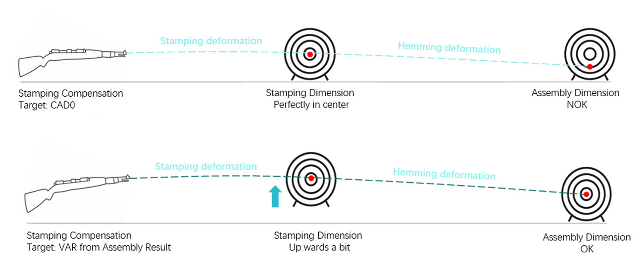
Fig. 1: Achieving dimensional requirements
Assembly Simulation Methodology
Although dimensional compensation of single panels based on AutoForm stamping simulations is widely used in the automotive industry, assembly-level dimension simulation and compensation are still rarely applied. In this article, a full-process workflow was established for a specific NIO vehicle model, covering both single-panel stamping and final hood assembly, using AutoForm Forming and AutoForm Assembly (Fig. 2).
After freezing the processes for the hood inner and outer panels, each panel was first compensated relative to its nominal CAD0 state. The compensated results were then exported into AutoForm Assembly for further analysis. Based on a predefined assembly compensation workflow, selected panels were further compensated to ensure that final hood assembly dimensional requirements were met. This article focuses on assembly simulation setup, compensation strategy, and comparison between assembly simulation results and real tryout measurements.
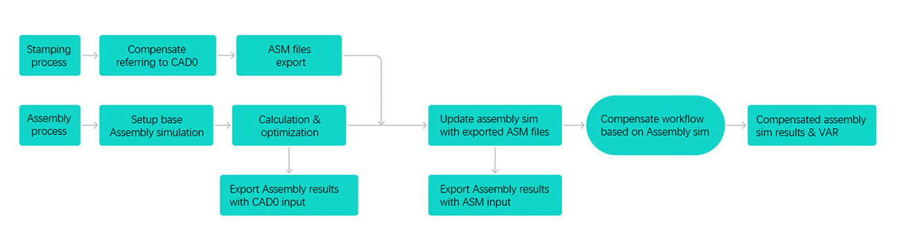
Fig. 2: Workflow
1. Assembly Simulation Setup
Based on CAD0 data, the AutoForm Assembly simulation file was created following a five-step workflow: part import and definition, operation planning, hemming definition and design, assembly process design and parameter definition, and calculation and optimization.
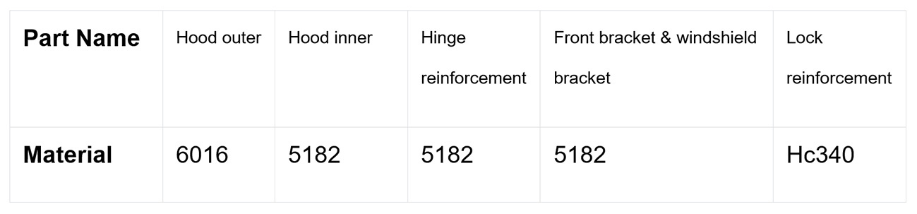
Part Import & Definition: Hood assembly data for each individual panel were imported and corresponding material cards were assigned.
Operation Planning: To reflect the real manufacturing process while maintaining simulation efficiency, processes that did not induce deformation were simplified or merged. The resulting operation plan included:
- Hood inner sub-assembly joining
- Pre-rolling of the outer panel to achieve an acceptable flange angle
- Hemming with a press die
- Glue curing
- Measuring
Hemming Definition & Design: Due to the large flange angle on both sides of the hood outer panel after stamping, a single hemming operation was not feasible. An additional pre-hemming operation was therefore introduced:
- Robot-controlled pre-rolling was applied in areas A to B to reduce the flange angle to below 100° prior to die hemming
- The hemming die first pre-bent the flanges to 45°to 55°,followed by final hemming to 0° around the hood perimeter
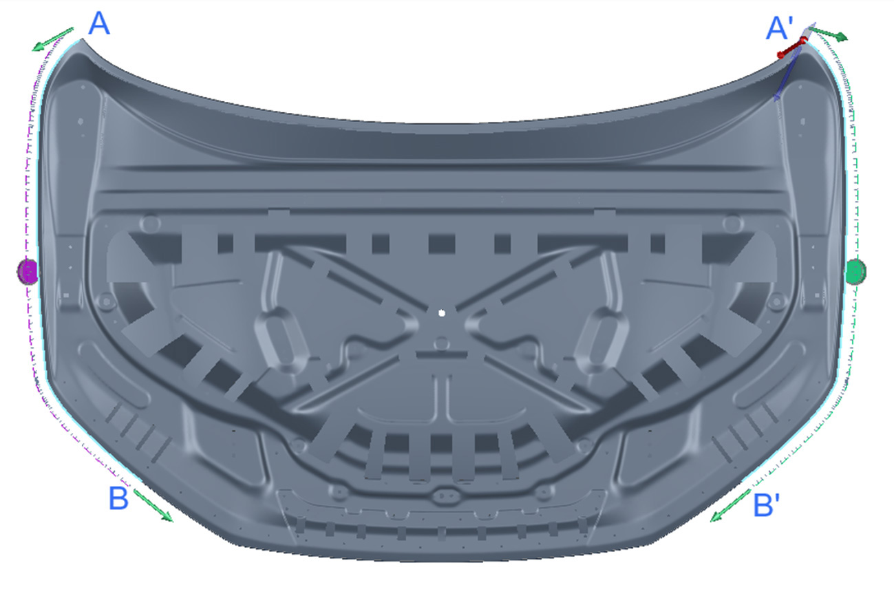
Fig. 3 Pre-hemming areas
Assembly Process Design
- Assembly components, including hinge reinforcement, lock reinforcement, front bracket, windshield bracket, and hood inner, were loaded and fixed on the AutoForm Assembly virtual fixture and joined using SPR to form the hood inner sub-assembly
- he hood inner sub-assembly was loaded into the glued hood outer panel, and pre-rolling was applied to reduce the outer panel flange angle on both sides to below 100°
- The pre-rolled hood assembly was loaded into the press hemming die to complete final hemming
Calculation and Optimization:After calculation and optimization, CAD0-based assembly dimensional results are shown in Fig. 4 and Fig. 5. Flush deviations were distributed as follows: bumper area maximum of -0.68 mm, middle of the front windshield area maximum of -0.849 mm, and hinge corner maximum of -1.2 mm.
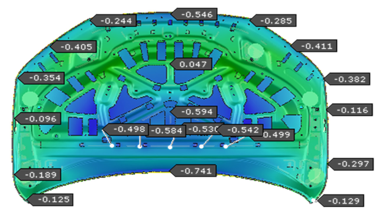
Fig. 4 CAD0-based assembly results (inner side)
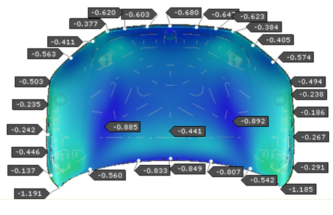
Fig. 5 CAD0-based assembly results (outer side)
2. Assembly Dimension Compensation
2.1 Compensation of Outer and Inner Single Panels
Single panels were compensated in AutoForm Forming based on the predefined stamping processes, using nominal CAD0 geometry as the compensation target. As shown in Fig. 6 and Fig. 7, the hood inner panel exhibited a maximum deviation of ±0.22 mm, while most areas of the hood outer panel remained within ±0.2 mm, with a small number of areas reaching ±0.56 mm.
The ASM results from these compensated forming simulations were then exported into the base AutoForm Assembly simulation to account for the influence of stamping history.
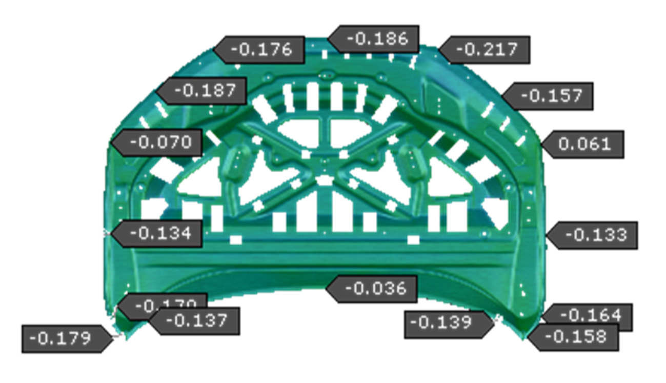
Fig. 6 Stamping compensation results of inner panel (refer to CAD0)
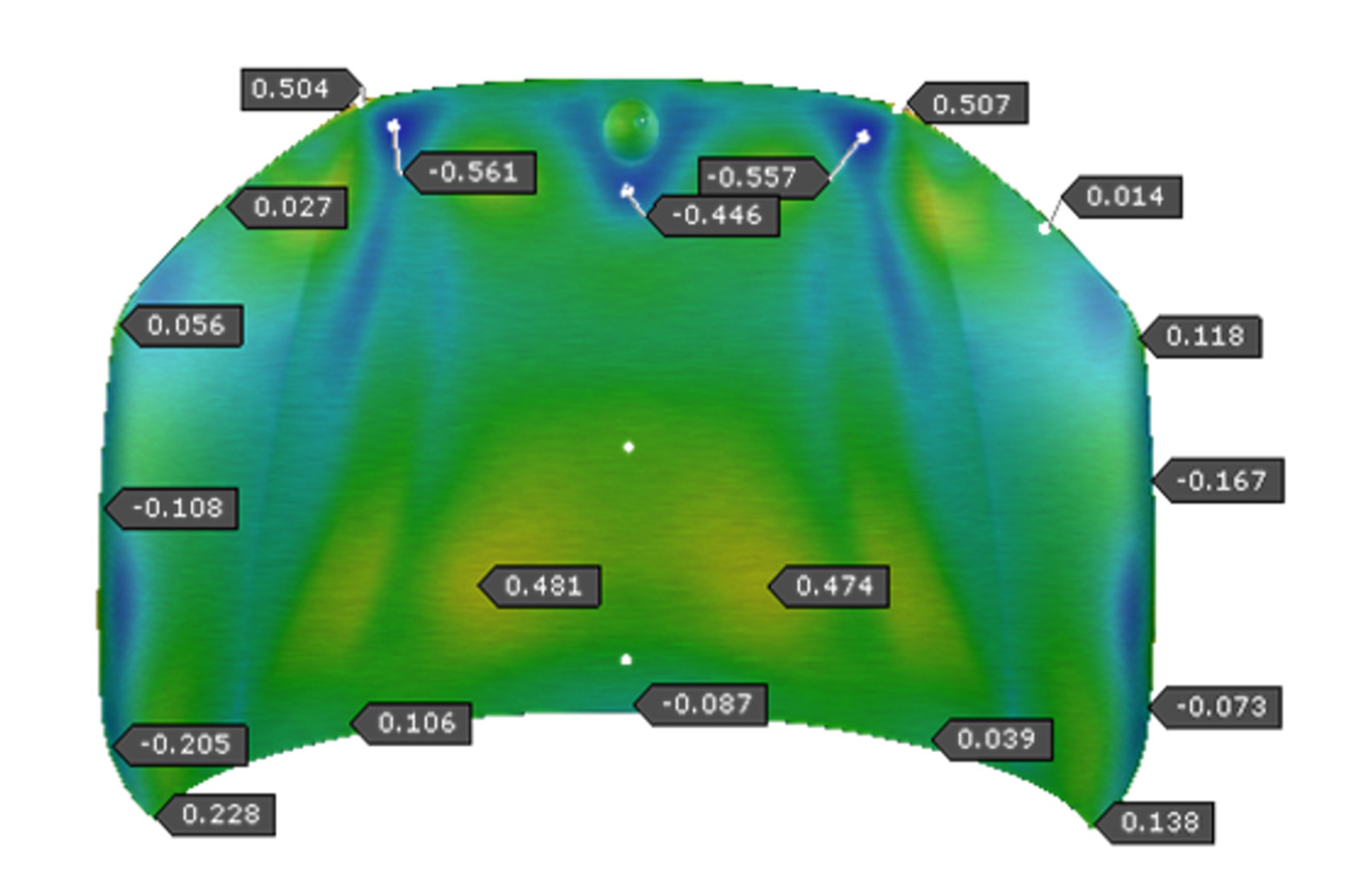
Fig.7 Stamping compensation results of outer panel (refer to CAD0)
2.2 Compensation Based on Assembly Simulation Results
Before starting assembly-level compensation, both the compensation target part and compensation workflow needed to be defined.
- Selection of compensation target part
Selecting the appropriate compensation target is critical for achieving a qualified assembly. Since the hood outer panel is a skin panel, maintaining surface quality during compensation is challenging. Therefore, the hood inner panel was selected as the compensation target.
2. Compensation workflow design
After selecting the hood inner panel, a compensation workflow was developed, as shown in Fig. 8. Based on this workflow, the hood inner panel was iteratively compensated using full assembly simulation results in AutoForm Assembly until a qualified assembly state was achieved. The compensated deformable mesh of the hood inner panel was then reconstructed into CAD geometry. This reconstructed geometry was used as the new target for hood inner compensation in AutoForm Forming.
A new ASM file generated from the forming simulation was imported back into the assembly simulation to validate final hood dimensional performance. If dimensional requirements were satisfied, the reconstructed hood inner geometry was confirmed as the manufacturing target. Otherwise, the compensation loop was repeated for additional iterations.
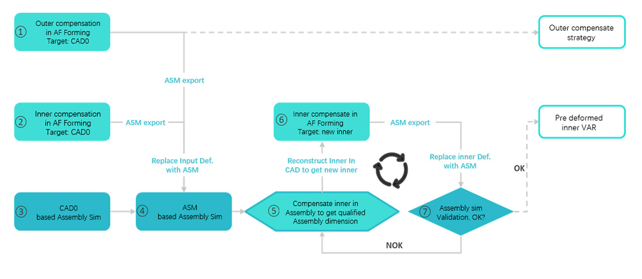
Fig. 8 Technical workflow of assembly-based compensation
2.3 Compensated Results and Hood Inner VAR Geometry
Figure 9 shows the compensated assembly simulation results for flush dimensions, with most areas within ±0.3 mm. Two hinge corner regions exhibited a maximum deviation of -1.38 mm due to non-mating CAD0 geometry between the inner and outer panels. This deviation is considered reasonable and cannot be corrected solely by compensating the inner panel. In practice, hemming tool compensation would be required to address this issue.
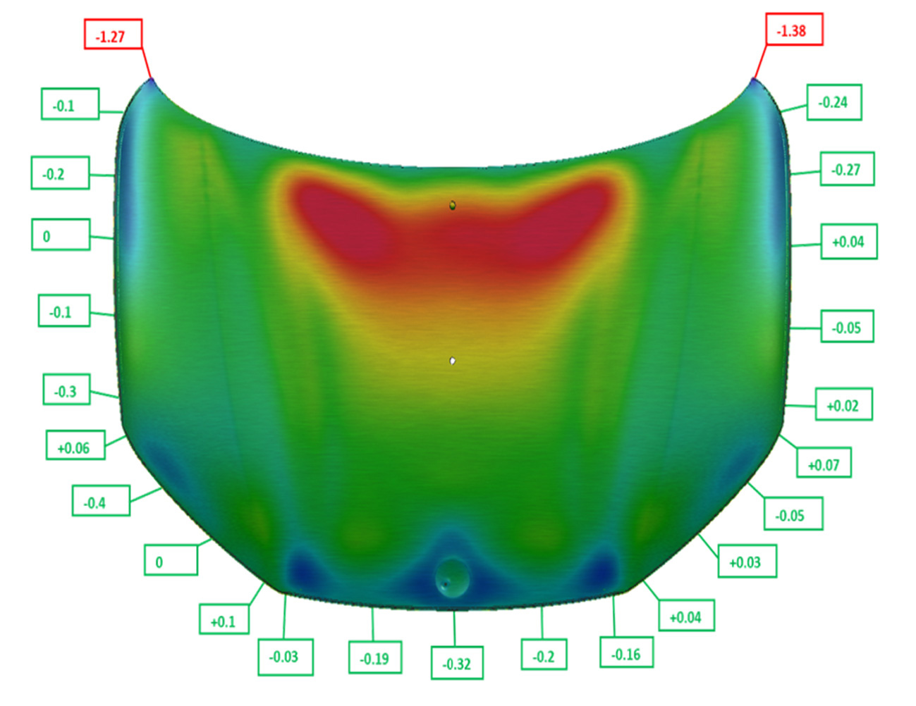
Fig. 9 Assembly compensation results
The hood inner geometry was then reconstructed based on its gravity-loaded mesh state, as shown in Fig. 10. Compared with nominal CAD0 geometry shown in green, the reconstructed VAR geometry shown in purple exhibited up to 1.1 mm of total pre-deformation in the lamp area.
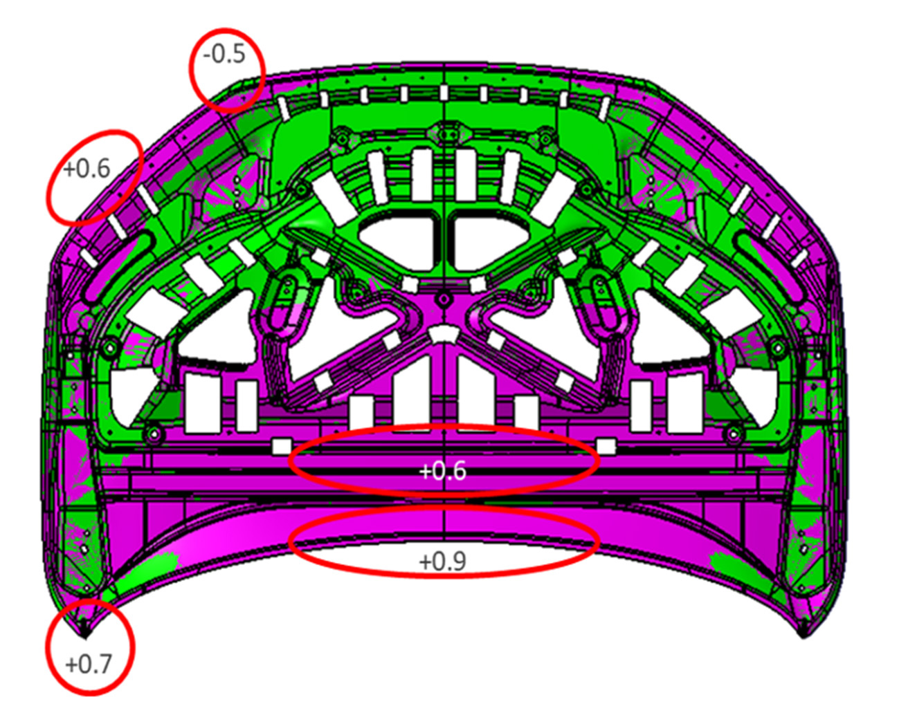
Fig. 10 VAR geometry (purple) vs CAD0 (green)
3. Comparison of Assembly Simulation and Real Tryout Results
Using the hood inner VAR geometry developed in this study, stamping tools were manufactured and single panels were produced. During the TT1 tryout loop, the assembled and hemmed hood was measured and compared with virtual assembly simulation results, as shown in Fig. 11.
84% of measurement points showed deviations from CAD0 within ±0.5 mm, while 88% of measurement points deviated less than 0.5 mm from the assembly-compensated simulation results.
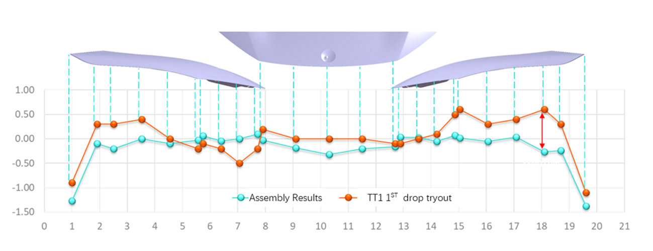
Fig. 11 Assembly simulation result vs tryout results
Summary
By combining AutoForm Forming simulation and AutoForm Assembly simulation, a comprehensive view of the full process chain from single panels to final hood assembly was achieved.
A new workflow was developed to generate qualified VAR geometry using assembly-simulation-based compensation methods.
In a real vehicle project, this approach achieved an 84% first-drop TT1 pass rate.
Through early analysis, early identification, and early pre-compensation of hood assembly dimensional issues, AutoForm Assembly provides an effective method for improving dimensional quality in BIW closure sub-assemblies.


?")


