
First Things First in Growing Your Accuracy Footprint
In part two of our series on using the AutoForm Pareto principle to improve simulation accuracy, we explain how to set up a forming simulation based on the AutoForm Accuracy Footprint concept and examine the essential process parameters — the first group of parameters covered in AutoForm’s Pareto principle model.
Series Index: Part 1, Part 2, Part 3, Part 4, Part 5, Part 6
As already demonstrated in part one of this series, the essential parameters account for around 80% of the final simulation result’s overall accuracy. We must keep in mind that process simulation is applied in engineering to predict what will happen in tryout and production — avoiding costly trial and error and rescue efforts further down the line. Therefore, an accurate simulation is one that correctly predicts the actual forming result. The accuracy footprint is a concept created by AutoForm, which can be applied to any sheet metal forming software to determine how accurate your simulation is. It provides a systematic process to check the quality of all the inputs and to ensure a consistently high simulation model quality.
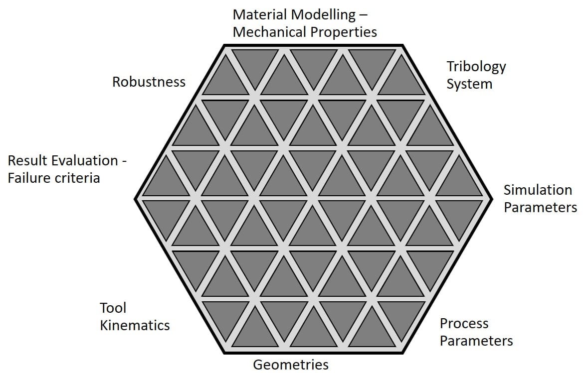
Fig. 1: Any discrepancies will result in a reduced accuracy footprint
Based on the accuracy footprint in Figure 1, we can address the parameters as input groups:
Material properties include the basics such as material grade, which defines the corresponding properties like yield, tensile strength, R-values, and thickness. We should also apply a representative material model in order to properly demonstrate the material behavior.
Tribology system represents the sliding interaction between the tool surface and the sheet. A representative friction model must be defined in order to describe the real physical behavior.
Simulation parameters: from a numerical or computational point of view, we must have the proper parameter set and use the right algorithms in element formulation and time step control in order to properly represent the characteristic phenomena of the verified application.
Process parameters include elements such as the definition of drawbeads, applied forces on various tools in several operations, as well as the proper blank and part location for each operation.
Geometries require verification that the data sets applied to the simulation match the latest released geometry. The end goal is to obtain the data set used for milling the tools because this is the physical geometry that will be created in reality.
Tool kinematics not only entail the stamping operation, press motion, ramp up and ramp down, but also the cam movements (including cam angles, etc.) — all of which must be properly represented.
Evaluation criteria dictates assessment of the simulation and experimental results. There are several criteria such as the draw-in, thinning and springback to verify the geometrical tolerance. Clear reference values must be defined and applied to evaluate the simulation results properly.
Robustness equates to the process precision or process capability. To be successful, we have to verify whether our process (i.e., our simulation result) is insensitive to any minor input variations. This is because we aim to produce many thousands of parts and our goal is to guarantee that every blank will consistently come out of the press as a correct part. Rather than merely a process point, we’re looking for a process window, which must also be verified to obtain accurate results.
Viewing our subject through the lens of the AutoForm Accuracy Footprint provides a proven framework to systematically identify and analyze the root cause of discrepancies between measurement and simulation. This is not only helpful for quickly identifying the cause of a mismatch, but also provides a proven tool kit to speed up tryout and improve future simulation setups.
Where the main application of the accuracy footprint is to verify the tool tryout, the Pareto principle is geared towards stamping engineering. Both concepts rely on a common base and adopt the same aspects — as we will unfold piece by piece in the remainder of this blog series.
Growing Your Accuracy Footprint — Beginning with the Essential Parameters
The AutoForm Pareto principle (see Fig. 2) provides the view that it’s best to achieve the required accuracy during development of the stamping process chain. In the previous post of this series, we determined that a group of essential parameters would achieve 80% of the overall accuracy for the process. These essential parameters form the basis for the simulation and once they’re properly defined, we’re already well on our way to achieving accurate simulation results.
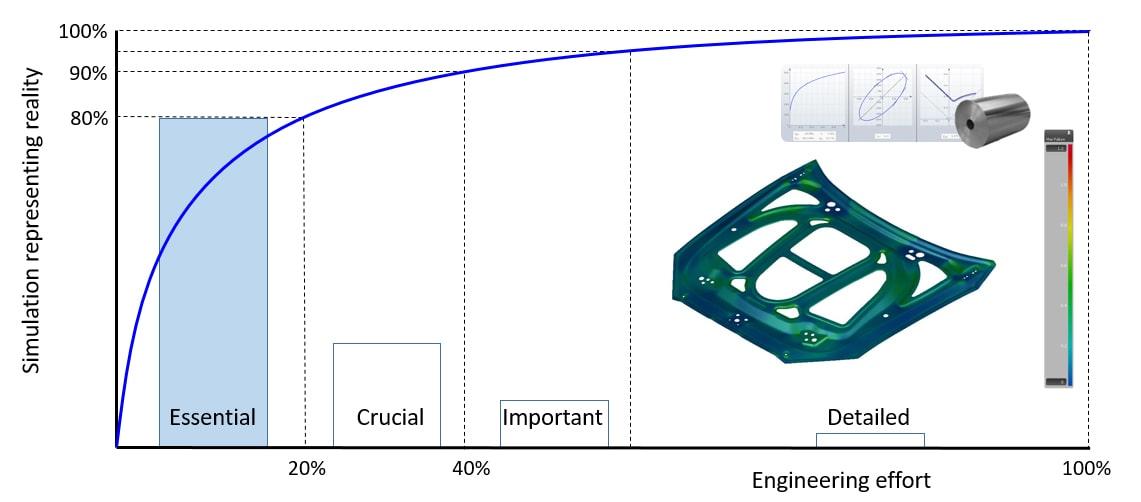
Fig. 2: The AutoForm Pareto principle demonstrates simulation inputs as maturing accuracy
By applying the AutoForm Pareto principle, we can increase the result accuracy by further focusing on additional parameters, so long as the following essential parameters have been secured first.
Process sequence is the first essential parameter to consider. All operations must be simulated according to the process plan. Shifting processing units to another operation can radically change the results. This means that stamping, trimming, forming etc. must all be considered in the proper order and work as a one-to-one representation of what will occur in reality, as this affects all subsequent steps. Therefore, the first and most important parameter to secure is a well-defined process sequence.
Tool kinematics are considered from basic, such as single action draw, press stroke, tool support during the stamping, etc. to specific, such as the tool movements in secondary operations — especially for cams and filler cams. Make sure you only simulate what can be built in practice. We must ask: can we actually apply these same kinematics in reality and can we apply the forces correctly on these specific tools? This should be verified at an early phase.
Tool geometries are included as essential parameters because during the whole development process you have to ensure you have the latest geometry release available for your simulation. This is the geometry that needs to be stamped and produced so always double check to ensure using relevant geometrical data. This is a frequent source of mismatches between the as-engineered and the as-built state.
Material properties such as the sheet thickness and blank shape are essential to define while ensuring you have selected the correct material grade. The blank shape is an input as well as a result of the engineering process. Blank shape must be controlled closely in order to keep the part cost under control. This entails evaluating the blank shape (and possibly blank nesting) and optimizing the material usage.
Numerical settings do the job of saying “enough is enough.” By applying the “Final Validation” setting, we can focus on the engineering job itself and not turn everything into a numerical exercise! The key is to not get caught up considering the fourth and fifth digit and, in so doing, lose sight of the bigger picture — as the process kinematics and the process itself are not yet properly defined.
Having secured the process sequence, tool kinematics, tool geometries, material properties including blank thickness and shape, as well as proper numerical settings, we now have a solid foundation to continue our engineering efforts.
At this stage, the formability results of the process simulations should already be in the “green” — i.e., the part should be completely free of splits and heavy wrinkling. At the same time, we need to guarantee the desired material stretch.
What we can see is that through these essential process parameters, the full process simulation is covered. And with that, we already have a solid base to achieve a very high level of accuracy, enabling us to stamp the real part (“as-built”) according to how it was engineered (“as-engineered”).
It’s important to realize that the essential parameters need to be defined properly and as precisely as possible at an early phase of the engineering process. They form the inevitable and fundamental starting condition for every simulation. These parameters also represent the aspects that are quite obvious and easy to compare in simulation to reality. On the one hand, it’s simple to transfer the simulation definitions to the stamping process, and on the other hand, it’s easy to measure or identify the parameters in reality. For example, consider the blank shape: It’s quite simple to determine whether or not we have correctly used the same blank in reality as in engineering.
Following the AutoForm Pareto principle, the “Guideline” functionality was created in AutoForm to help set up accurate simulations systematically and consistently. For an efficient process definition, start with the conceptual stamping process feasibility, which covers all of the essential parameters. The software guideline in AutoForm prompts you to amplify your accuracy footprint by looking into the full stamping process feasibility and validation in the proper sequence.
An efficient process definition starts with the guideline “conceptual stamping process feasibility,” followed by the guidelines “full stamping process feasibility” and then “full stamping process validation.” This last guideline is dedicated to the setup of the final simulation, representing the future die try-out. The subsequent guidelines in AutoForm support the stamping process chain and systematically cover leveraging the AutoForm Pareto principle to improve simulation accuracy.
In the next blog post of this series, we focus on the crucial parameters, which are validated. If you found this contribution interesting, sign up to our blog or return soon for further installments of this multi-part series.


?")


