
The Next Phase in Growing Your Accuracy Footprint
This is part four of our series on using the AutoForm Pareto principle to improve simulation accuracy. In this post, we explain how to set up a forming simulation based on the AutoForm Accuracy Footprint concept and examine the important process parameters — the third group of parameters covered in AutoForm’s Pareto Principle model. Our application of the Pareto principle to forming simulation delivers a working approach to determine which groups of parameters are significant, and which are not quite as significant, to the accuracy of the final result. By applying this prioritization, we can systematically and consistently evolve our simulation towards increased accuracy as more details are chosen or become known through the development and engineering process.
Series Index: Part 1, Part 2, Part 3, Part 4, Part 5, Part 6
Having already secured the essential parameters and the crucial parameters in our two previous posts, we now have a solid base for the simulation,as these two groups account for 90% of overall accuracy for the final simulation results. As the next level, important parameters deal with fine-tuning the process setup. There are two key reasons why working in this phase commences only after securing essential and crucial parameters.
Firstly, the important parameters build upon the essential and crucial parameters. For example, if you change a crucial parameter, you have to fine-tune the important parameters all over again. Consider that you define a drawbead (location and restraining profile) to control the material flow, based solely upon the representative material behavior (properties and model). Of course, this drawbead definition has an impact on the resulting required process forces. Therefore, if you change any one of these essential parameters, the important parameters, such as the required amount of binder force, will also change.
Secondly, the result variation caused by any modification (fine-tuning) of the important parameters is quite small compared to the variation caused by modifying the crucial parameters. Tribology, for example, is relevant wherever sheet and tool are in contact, whereas the bearing area defines where the friction acts in the binder area itself. The definition of bearing areas therefore generally has a local effect. Hence, the friction model needs to be defined first —before analyzing the effect of a bearing area on the results.
All of this means that during the engineering process, our simulation and the stamping process definition are becoming increasingly concrete and well-defined. The process definition steadily matures as one parameter set builds upon the last. Consequently, some of the already defined essential and crucial parameters can be more precisely defined, allowing for further fine-tuning at this point. Yet, we have to ensure that we are already certain of the values in these two parameter families.
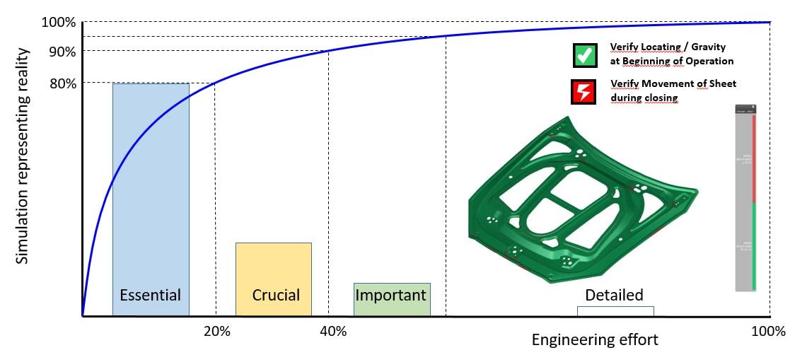
Fig. 1: Our Pareto diagram has progressed to the important input phase
The focus of the below important parameters is on the representation of the real process sequence. Each step in the process should be represented in simulation as realistically as possible:
Gravity: Gravity acts while positioning the initial flat sheet on the binder. In this stage, the only force acting on the sheet is gravity. Depending on the binder shape and the optional punch support, the exact position, shape and sagging of the blank is defined by the gravity force. The position of the pilots should be defined in order to locate the blank with precision and repeatability. This exact location and sagging can influence whether wrinkles will occur or be prevented during binder closure and at first punch contact. Of course, this only makes sense if the geometry of the tools has been properly defined. The sheet and blank shape should be defined or else the gravity will be an arbitrary value.
Intermediate Springback: This should be considered at the end of the operation where the part is deformed. The induced stresses cause the part to slightly change in geometry. This slightly altered part geometry is located in the next operation and the manufacturing sequence continues. Since the resulting geometry depends on the amount of springback, this step should be included in the simulation. The subsequent part locating and tool closing might slightly deform the part if it does not perfectly match the geometry of the subsequent operation.
Blank/Part locating: What was mentioned regarding the positioning of the blank in the draw operation also applies to the formed part in the secondary operations. The part will be positioned onto the tool and gravity will define its exact location. If the part geometry and pad/post geometry are not an exact match, the part will not completely nestle into the tool. Thus, pilots may need to be defined in order to reproducibly specify the part location and to avoid further unwanted deformations.
Tool closing: Its important to account for the closing process, especially in multiple operation processes, to properly take intermediate springback into consideration. The closing may cause deformation and changes to the stresses and strains. Sometimes, these reactions are extremely sensitive to small changes in stress distribution. Therefore, in order to achieve an accurate springback control, we must accurately simulate the whole sequence.
The sequence of gravity, intermediate springback, blank-part location and tool closing is important to take into account to understand the complete stamping process. These four important parameters are strongly linked and should be defined altogether. Although they influence the final result, their definition and fine-tuning only makes sense if the overall process has already been properly defined, especially the final shape of the blank and binder. The overall process is defined by the essential parameters (process sequence, definition of all operations, tool geometries, and tool kinematics) and crucial parameters (material, tribology and drawbeads)
In reality, there are other constructive measures taken into account, which should also be represented in the simulation:
Bearing area: In order to ease the binder spotting, a ‘partial bearing’ can be applied. In this case, the binder only acts upon a certain area – outside this area, no binder-sheet contact occurs. As a result, only this select area needs to be spotted, and we all know that spotting is a timely, costly and cumbersome process. The less we have to spot, the faster and cheaper the tool tryout will be. On the other hand, when the binder only acts upon a specific area instead of on the complete binder area, the pressure distribution will differ and consequently, the friction resistance will differ, again influencing the material flow. Hence, bearing areas have to be accounted for in the simulation since we want to represent the material flow during the stamping process as realistically as possible.
Realistic process forces: Applied forces or occurring reaction forces should be evaluated carefully. One should analyze whether these forces can be applied in reality. Is my press strong enough? Can I build in the required gas or nitrogen springs? Can the tool construction carry such forces and can I design a cam capable of carrying8 metric tons (80 kN)? We must always keep in mind to “only simulate what can be built in reality.”
The important parameters undoubtedly influence the final result. However, they cannot be manipulated to control the forming result. They just happen! One cannot switch off gravity nor suppress springback. However, one should incorporate and account for such effects at this point because they impact the final result.
Until now, we have only focused on a single simulation. However, we know that not only the process feasibility is important, but process capability as well. The remaining important parameter, process robustness, is discussed in the next installment.


?")


