This blog post discusses the topic of forming a blank containing a patch. While the shape and position of the patch on the part is determined by design and verified by a test engineer, the forming process makes determining the patch outline on the unformed blank a little more difficult. The required know-how undoubtedly exists among process engineers, but we were interested to know which methods are most commonly used for this purpose, along with the inherent advantages and disadvantages of each. To find out, we interviewed users from all over the world, from different companies that use different software applications. Our interviews came back with three different approaches that provide satisfactory results:
- Formcheck
- Tracking of Material Lines
- Automatic Trimline Optimization
First we will briefly introduce these three approaches before providing a comparison.
Formcheck:
Formcheck is a one-step inverse simulation and analysis tool, which allows an initial evaluation of different parameters, such as formability, and also develops the part into the desired plane. In this way, the necessary blank geometry and patch outline on the blank are both obtained. With minimal input parameters, the modeling and calculation efforts are very low, requiring only about 1 – 3 minutes to provide an initial estimation of the shape and position of the patch on the blank.

Figure 1 – Formcheck
The evaluation of a test series shows that a patch geometry on the formed component determined in this way has an average deviation of about 2 mm and a maximum deviation of about 2.5 mm from the target line.
Tracking of Material Lines:
This method requires an initial “dummy” simulation without a patch. The desired outer contour of the patch geometry is then projected onto this result. That line is then automatically assigned to fixed material points on the blank, making it possible to backtrack in the simulation to the initial blank. This fixed assignment now provides the position and shape of the patch on the initial blank.

Figure 2 – Tracking of Material Lines
Since the shape and position of the patch influences the result of the simulation, the determined patch outline depends on the quality of the initial simulation. The deviations from the target patch on the formed part are similar to those achieved with Formcheck, i.e., about 2 mm on average and about 2.5 mm at the maximum.
Automatic Trimline Optimization
Automatic Trimline Optimization on the incremental forming simulation is an iterative method for optimizing trim and outer contours. The underlying principle is a comparison of the existing inner and outer contours on the formed part to a respective target line and a subsequent adjustment of the trim and outer contours based on this comparison. This iterative process is repeated until the desired boundary curves are all within a self-defined tolerance window. This method is entirely automatic.
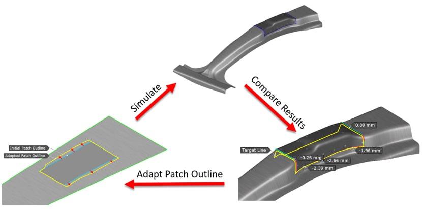
Figure 3 – Iterative Process of Trimline Optimization
With this approach, an initial guess of the patch outline is required. It would be conceivable to use Formcheck for a first estimation of the patch outline, since no initial simulation is necessary and it works very quickly. The accuracy of this method can be determined by a defined tolerance window. With a moderately realistic tolerance window (e.g., +/- 0.25 mm from quality specification), usually 2 – 3 iterations are needed to achieve the desired result. Since this iterative process continues until the defined tolerance is fulfilled, this approach provides the maximum possible accuracy for the consecutive assembly process.
Comparison of the three approaches:
If we now compare these three approaches, we find that a simple evaluation according to “better” or “worse” is not possible. The evaluation based on one parameter, such as dimensional accuracy of part geometry, is insufficient here, because the time factor of the engineering phase plays critically on the levels of information. As we all know, most engineers are working along the broader engineering process chain and must therefore complete the job in a timely fashion for consecutive flow. Engineering time is an enormously important resource that should not be wasted. So rather than asking “What is better?” — the question should be “What is better WHEN?” That gives us a more realistic basis for assessment. The question “When?” is answered by looking at the digital engineering process chain coupled with the physical engineering process chain and the level of accuracy differently required in the individual phases.

Figure 4 – Digital engineering process chain and the differing accuracy targets among phases
It can be seen that in the early phases, such as initial feasibility testing or planning and bidding, accuracy plays a rather subordinate role or cannot be feasibly high owing to the many undetermined parameters. In these process phases, the methods “Formcheck” and “Material Lines” would therefore be appropriate, as they are less accurate but provide a result very quickly. In a direct comparison of these two methods, Formcheck is the winner, since it takes a little less time while the quality of the result remains approximately the same.
In the final phases of the process chain, such as final validation or determination of the exact tool geometries, the highest possible accuracy is required. Trimline Optimization is therefore the method of choice here, even though 2 – 3 simulations are required to provide the desired accuracy.
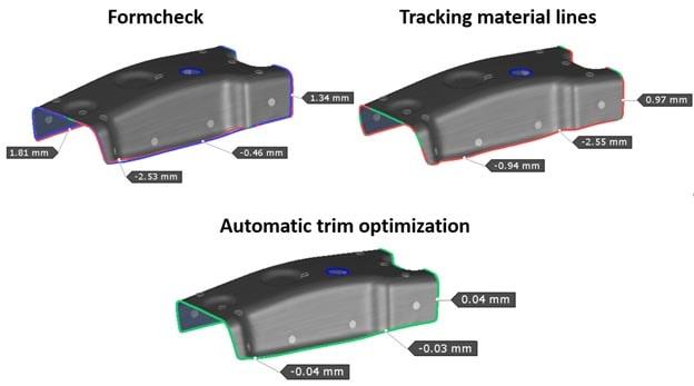
Figure 5 – Comparison of accuracy
In summary, these approaches have different strengths, either based on required time or accuracy. So it is up to the process engineer to decide which parameter is more important depending on the current process stage and to choose the most suitable approach. In order to secure this accuracy evolution along the engineering process chain, each engineering outcome must be consistently associated with the shared engineering parameters.


