
Why does the engineering framework need a standardized structure aligned with design and engineering processes?
Have you heard a sentiment to the effect of, “The quality of tools dictates the quality of the craftsman’s work”? Of course, the use of high-quality professional tools positively impacts not only the work itself, but also the finished product. This also holds for engineers who need to rely on the best software tools to get the job done well.
Today, software plays an important role in systems engineering, the interdisciplinary approach governing the total technical and managerial efforts required to transform a set of demands, expectations, and constraints into a solution to achieve the goal of “real” engineering. Professional associations and standardization organizations have defined guidelines for engineers on how to assess the quality of their processes and engineering tools — such as the quality management principles described in the ISO 9001-2015 fifth edition standard.
Engineering is generally a highly collaborative effort involving professionals from different teams and departments. Hence, following the process approach of ISO 9001-2015, engineers need software tools that support effective and consistent collaboration across the entire organization.
So, logically, the first questions we need to ask are:
Where can we find the right engineering software tools to support the real engineering process?
Furthermore, how can we assess the degree to which a specific software tool supports collaboration?
The second question can be addressed using the standard ISO/IEC TR 24474:2021 Systems and Software Engineering – Life Cycle Management – Guidelines for Process Description – Guide to the Software Engineering Body of Knowledge (“SWEBOK”).
One important concept outlined in this standard is consistency, which in this context concerns the degree to which the computer model used to simulate the manufacturing process (stamping, BiW assembly, etc.) is free of conflicting or incompatible requirements, assertions, constraints, functions, or component descriptions in all knowledge areas. Additional aspects of consistency are the suitability of the software technology to meet the analysis objective and the reliability or accuracy of the input data. Naturally, the algorithm accuracy will be commensurate with the input data reliability and modelling accuracy. An example of violating this type of consistency would be the use of rough estimation algorithms on highly mature and accurate input data, and vice versa.
Useful methodologies to analyze software consistency include the AutoForm Accuracy Footprint concept (https://formingworld.com/autoform-accuracy-footprint/), and the AutoForm Pareto Principle (Part 1, 2,3,4,5,6: Link to FormingWorld.com blog publication).
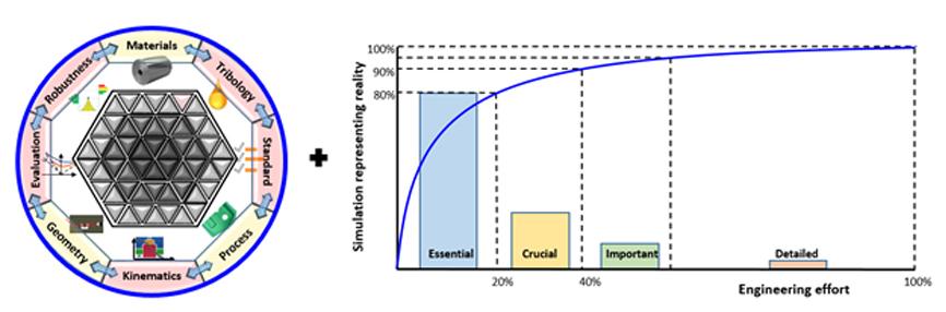
Fig 1. AutoForm Accuracy Footprint and Pareto Principle for stamping processes
The AutoForm Accuracy Footprint contains 8 essential aspects of creating consistent, valid, and accurate computer models of stamping and BiW production processes:
- Material Specifications
- Tribology Systems and Friction Modelling
- Simulation Standards
- Process Definition
- Machine Kinematics
- Tool, Part and Fixture Geometries
- Result Evaluation
- Process Robustness
These 8 aspects all need to be satisfied to achieve the engineering objective and will continuously evolve during the development and engineering process.
Process aspects such as draw bead design and die surface layout can be defined using the material specs and part geometry provided as initial conditions from part or product design. However, the primary job of a process engineer during subsequent process feasibility studies is to update the geometries (including part geometry) with tool kinematics and to further develop or update new process aspects to achieve the necessary part quality for future production based on the evaluation standards.
Importantly, these updates need to satisfy the engineering goal of robustness with realistic inputs of the variations of production conditions (e.g., tribology, tool clearances, parameter variations, etc.) and proper evaluations. These updates to the computer model take place throughout the entire engineering process, as Bart Carleer describes in his post covering accuracy during the developing process using the AutoForm Pareto Principle for sheet metal forming engineering.
To support engineering collaboration, the software system architecture must address all aspects of the AutoForm Accuracy Footprint. In addition, the software architecture needs to be consistent with the physical engineering work flow.
In terms of a hierarchical software structure, the system, subsystems, components, and units should reflect the reality of engineering aspects during the verification and validation process, as shown in Fig 2
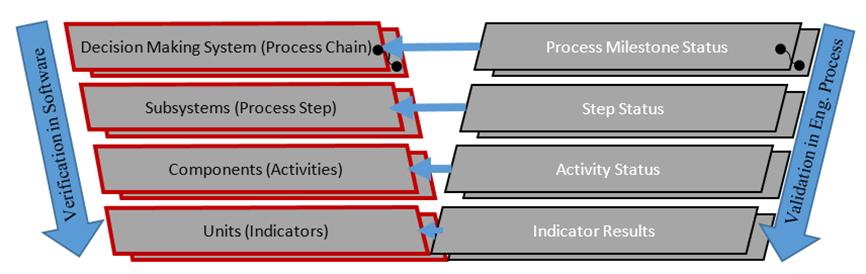
Fig 2. Sequential systems engineering & hierarchical software Vee model (data structure)
The use of simulation setup standards (generally validated through intensive testing) is a cornerstone of the AutoForm Accuracy Footprint. The AutoForm guideline files provide standardized setup, satisfying a general principle of systems engineering, namely that the software system must be based on a workflow model of the actual development and engineering process (e.g., use of the AutoForm Pareto chart). The allocation of software features (accuracy aspects) in the software simulation standards follows the engineering decision making process rather than function- or component-based architecture. At first glance, Fig. 2 seems to show a function-based and hierarchical diagram. However, if we look carefully at the top layers and think about the decision making process along the process chain, we recognize that it actually shows another hierarchical structure inside an object (methodology)-oriented structure. This hierarchy of decision-making structures must ensure the consistency of process improvements based on the right decisions.
The AutoForm software system provides standards for different engineering phases with decision-making aspects at important milestones and along the entire process chain. For instance, the simulation application standard settings CE (Conceptual Engineering), CE+ (Conceptual Engineering plus), and FV (Final Validation) are aligned with different engineering phases from early feasibility to final validation. They are automatically aligned to support the selection of the proper simulation parameters for relevant engineering aspects conforming with the process phases. These setups are consistently validated with real aspects of the AutoForm Pareto chart. The concept of consistency in software systems engineering forms the core of the comprehensive integration scheme in AutoForm’s software:
- Combined classical function-oriented, component-based, and object-oriented software design strategy.
- Systematic integration strategy based on the real engineering decision-making process driven by the hierarchical software architecture.
- Self-verification-validation Vee model for consistent systems engineering: verification in the software on the left mirrors the validation in the systems engineering process on the right; AutoForm provides guidelines and standard files directly embedded into the design file for customer validation processes.
In software testing after unit testing, top priority is the integration consistency — the process of verifying the interactions among all software components. To check the hierarchical structure of integrated systems, the top-down and bottom-up approaches are often used. AutoForm, however, follows a comprehensive, modern, and systematic integration strategy using both the Accuracy Footprint and the Pareto Principle. Integration testing is ongoing at each application stage of the real engineering work flow. The self-verification-validation Vee model is typically adopted as an efficient and effective methodology for consistent systems engineering.
To summarize, consistency is the most important software testing element to check the performance of integrated systems engineering and validate the software standard data structure. The following aspects need to be considered regarding consistency:
- How much software is sufficient to achieve the stated engineering objective or goal.
- The degree to which the model contains conflicting requirements, assertions, constraints, functions, or component descriptions in all knowledge areas.
- The Vee model used in sequential systems engineering and hierarchical software is a self-correcting process of verification and validation between software system and physical engineering work flow.
- The AutoForm Accuracy Footprint and the AutoForm Pareto Principle can be used directly to ensure consistency of the simulation and the setup.
- AutoForm software systems engineering consistently supports the goal of physical stamping systems engineering.
Stay tuned – in the next post in this series, we will expand on smart engineering concepts, concentrating on the prediction capability of digital process twins in terms of process, software, and model accuracy. In particular, learn how we can efficiently realize digital twins based on the forward engineering approach and the important issues we need to focus on for the greatest success.
For now, you may also wish to view our video, “What is the Right Way to Understand Accuracy? A New Argument – A New Way of Thinking!”


?")


