[dropcap]I[/dropcap]n this article we demonstrate the finalization of process conditions for a hotforming process using images from AutoForm’s unique ‘tryout-mode’ which allows for adjustments to quickly be made during simulation. With lightweighting on the rise hotforming is a hot topic. Here is one way to get meaningful and reliable guidance from virtual engineering.
Instead of relying on digital engineering and validation late in the game, OEMs are leveraging these tools from early on, through every stage of the die / process engineering timeline. Today design assessments incorporate changes and ‘likely situations’ that may arise during concept to process engineering phases.
The state of the art multi-faceted approach to simulation covers for various scenarios, as opposed to past methods which were capable of producing only one-off forming process validations. Results are no longer set in stone, as tools may be used to manually optimize the results in such a way that is meaningful, for example: can it be more cost effective? If not how can we customize the solution to meet our targets?
The old method of adjusting process elements based on experience meant that initially a simulation was trialed, and if its feasibility was less than perfect the process was repeated. We know this is time consuming, but worst of all – a solution might never be found. Furthermore, mistakes made with respect to the water cooling concept in the tools are usually impossible to be predicted for every single spot on the contact surface, and apart from that impossible to be fixed in the existing tools. So, under these conditions, the tools’ features are per default subject to serious oversizing in order to add necessary safety margins.
Instead of taking a simulation result as a fatalistic prophecy of doom, (as if a user is limited to accepting a result as final) we can indeed ‘play around’ with the alternatives in virtual tryout mode, instantly evaluating outcomes resulting from process adjustments being tried out. No longer limited to black boxes which deliver frozen outcomes, you can now get into the black box for a systematic and prioritized search for cost-quality-time optimized process combinations.
Such a systematic approach starts with the definition of meaningful and plausible “windows” for each controllable process condition; each of these process windows is then computationally explored in combination with all others, automatically generating data and information on the influence – independent and joint – on final outcomes. Desirable cost / quality / timing targets are also laid out upfront. The data and information generated is then leveraged, over live and virtual tryout, to systematically build process combinations that are capable of achieving targeted outcomes. The live and interactive nature of this virtual tryout starts from a numerical optimal process combination, and improves this into the best practical solution achievable.
Systematic Process Improvement in Tryout Mode
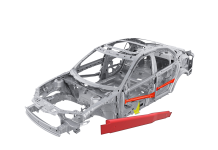
So how does this look in practice? For the part under consideration, a hot formed B pillar, we’ll look at design variations (process elements) and the ranges (adjustment windows) explored. We will neglect more advanced options for modelling cooling channels in the tools and the prediction of the thermal cycling behavior. We will represent a typical rework loop in a concept validation for the given part. Does this part fit into the parameter range of my equipment? Do I need to take care of specific pitfalls?

The quality targets to be achieved were: thinning < 17%, martensite > 98% and no wrinkles.
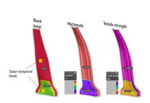
The Martensite:

Freedom to optimize process for Martensite without compromising Thinning

Martensite sliders show suggested settings. Once it is confirmed that the necessary volume fraction of Martensite can be produced, it is possible to manually explore settings for reduced cycle time, fixed binder gap, minimum quench tonnage etc., while preserving desired Martensite levels; this is made possible by identifying those process conditions that show minimal influence on Martensite, but which pack a stronger punch when it comes to the other “desirables”.
Reduced cycle time:

Here the quench and transport time are set & locked at their shortest, the binder gap and in-die quench are force locked at standard levels, and the suggested settings for tool temperature – let’s consider this as the case of regular cooling efficiency – are given at 60oC, and for the blank temperature 861oC is generated.
The question then arises: Can the tool temperature be increased – as this could occur under worst case conditions and if so, how high? And then what should the corresponding blank temperature be raised to in order to stay in range with respect to the desired part quality?
Increased Tool Temperature:

With tool temperature set to the highest value of the explored range, 85oC, the Martensite development is reduced if the original blank temperature (861o) is retained. However, virtual tryout suggests now to heat blank to higher temperature to restore desired Martensite level, all else held the same. In fact, from the image below it is seen that a blank temperature above 900oC, and up to 950oC, is capable of restoring Martensite volume fraction to desired levels over the entire part.
Increased Tool Temperature and Blank Temperature:

The natural, and practical, choice is to keep blank heated to the minimum temperature to accomplish the job.
Confirm Wrinkling/Compression for new settings
The above combination of process conditions, developed systematically, needs to be carefully validated for target outcomes on secondary part quality metrics such as wrinkling / compression.

Success: no wrinkles in critical areas, and minimal waviness along sidewall, thus the changes are acceptable as a compromise.
Review / validate Robustness of new process: (against blank gage and lubrication variations)
However systematically / intelligently the above process is finalized to satisfy prioritized targets, it is important to confirm that uncontrollable production conditions do not cause the final part quality outcomes to stray outside of specified and acceptable tolerances for these: It is necessary to validate the “robustness” or “repeatability” of finalized process.

Cpk validates Thinning as <17%, and Martensite at >98%.
Review / validate Robustness of new process: (against blank gage and lubrication variations)

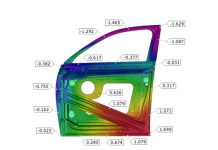
Distortion on nominal is within the desired tolerance of +/- 1mm. Cpk validates dimensional compliance of +/- 1mm.
A new process was established and validated for “Process Capability” (robustness)
“Digital engineering and validation tools need to faithfully represent the physical die and process elements of production conditions; they need to be capable of processing complex forming conditions; and they need to provide all necessary diagnostics, as well as meaningful turnaround and interactivity to in order to empower, even embolden, engineers towards product and process innovations” Kannan Kidambi AutoForm USA.
This blog-post reviewed the state-of-the-art capabilities available today, and illustrated a step-by-step application of these capabilities to a hypothetical, but commonplace, engineering challenge.
To get more articles like these, subscribe to our blog for more. We do not share your personal information and we do not send any marketing emails. You will only receive blog post updates.


