
Aiming at cracking and wrinkling issues occurring during the stamping of floor crossmembers with typical structural features, this paper analyzes the causes of these defects through AutoForm simulation. The product structure and forming process are optimized in accordance with body assembly layout space, lap joint relationships, and collision strength requirements. The proposed solutions effectively eliminate cracking and wrinkling defects.
The automobile floor crossmember is typically located in the front, middle, and rear sections of the body-in-white chassis. It forms part of the chassis structure by connecting with other structural components such as floor panels, body longitudinal beams, and floor crossbeams. As an important connecting component of the body-in-white frame, it plays a key role in the overall body structure.
Floor crossmembers are generally manufactured from high-strength steel. The bottom flange surface, end vertical surface, and top connecting surface are joined to the floor, the side wall, and the upper surface of the body longitudinal beam through spot welding. To improve load-bearing capacity, impact resistance, and torsional rigidity while enhancing body safety and chassis stability, floor crossmembers are often designed with closed structures at the connection surfaces to avoid tearing at notch locations during collisions. However, this closed design increases the difficulty of the stamping process.
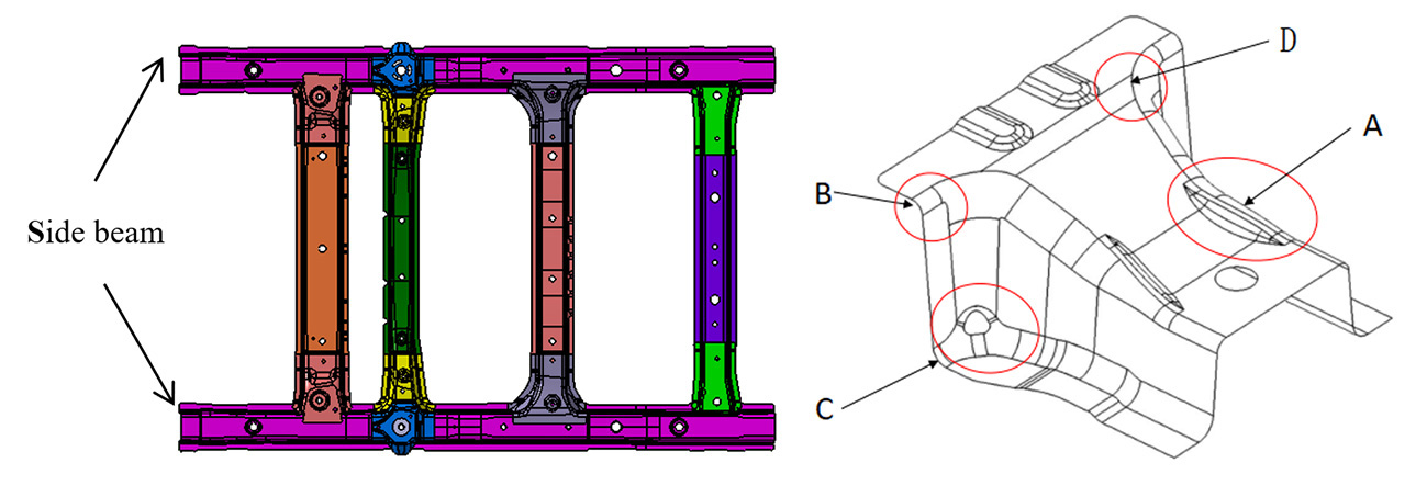
Fig. 1: Connecting plate application Fig. 2: Typical structure and defect location
1 Product Structure and Stamping Process
To ensure structural strength, materials such as B340LA or higher grades are commonly used. Compared with conventional sheet materials that have good elongation, high-strength steels exhibit higher yield and tensile strengths but lower formability. As a result, the allowable thinning rate in a single stamping operation is relatively low, making cracking more likely during forming.
The typical structure of the part is shown in Fig. 2. Considering both material utilization and the complex trimming structure on the side with a small vertical draft angle, a blanking and forming process scheme is adopted.
The main forming challenges include:
- Wrinkling in region A
- Cracking in regions B and C
- Wrinkling in the upper corner of region D
2 Forming Defects and Process optimization
2.1 Wrinkle at the Concave of the Top High-Low Drop
To increase the internal space of the vehicle body, the longitudinal beams on both sides of the body are positioned higher than the middle crossbeam. As a result, the floor crossbeam connecting plate includes an inclined surface with a height difference.
In the concave fillet transition area between this inclined surface and the crossbeam connection region, a noticeable radius ridge protrusion and material overlap occur in region A during forming. This results in visible wrinkling and surface unevenness on the side wall, which cannot be completely eliminated. Although increased flange pressure can slightly reduce the wrinkling, it cannot fully resolve the defect, as shown in Figs. 3 and 4.
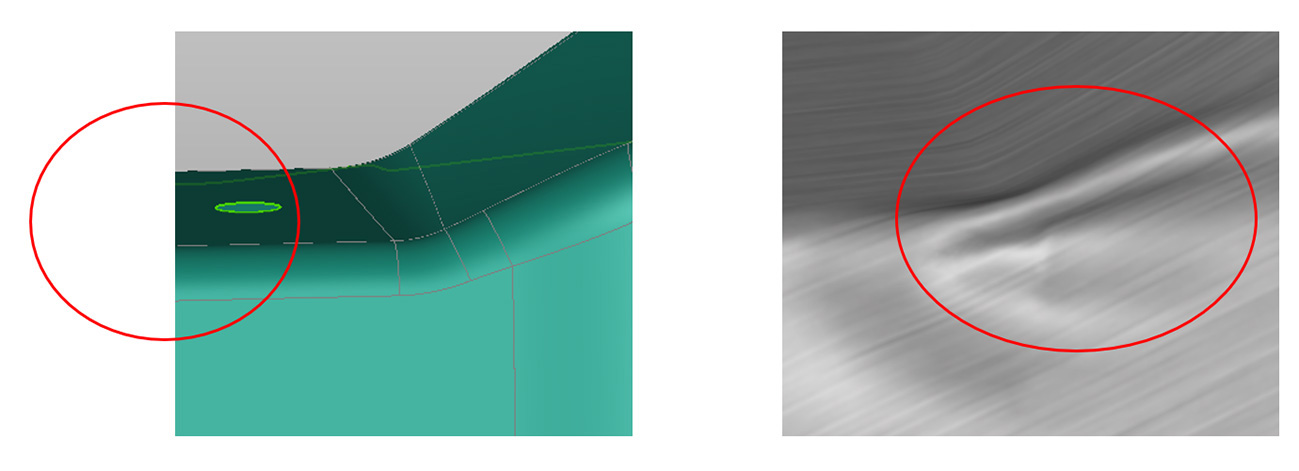
Fig. 3: Product structure at defect location Fig. 4: Simulation analysis results
Based on the defect formation mechanism, the main optimization measures include:
a) Reducing the height difference at the top step.
b) Increasing the transition area between the high and low surfaces to create a smoother transition.
c) Adding gainer features to absorb excess material and reduce wrinkling.
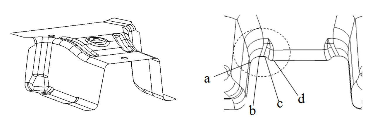
Fig. 5: Product optimization example Fig. 6: Product optimization example
As shown in Fig. 5, the feasibility of scheme (a) depends on the body structure, particularly the height relationship between the longitudinal beam and the crossbeam, which leaves limited adjustment space. Scheme (b) offers greater flexibility by increasing the transition area. Extending the transition surface toward the limit position of the lower surface ensures sufficient functional margin for welding surfaces or holes. In addition, this approach can be combined with adjustments to the trimming position of the floor crossbeam.
Scheme (c) increases the sectional line length by adding gainer features that absorb excess material during flanging. As shown in Fig. 6, a raised feature along section a–b–c–d is introduced. To prevent upward warping of the blank after blank-holder pressure is applied, the gainer is designed with a flat section (b–c) at least 5 mm wide.
2.2 Cracking at the Upper Corner Radius of the Longitudinal Beam
To ensure connection strength, the floor crossbeam connecting plate is welded to both the upper surface and side wall of the frame longitudinal beam, as shown in Fig. 7.
During stamping, the top surface is held by the blank holder while flanging inserts press the blank downward for forming. At the corner radius, where the sheet contacts the punch, the material experiences concentrated loading. A significant tearing force develops at the seam allowance along the radius edge, which can lead to cracking.
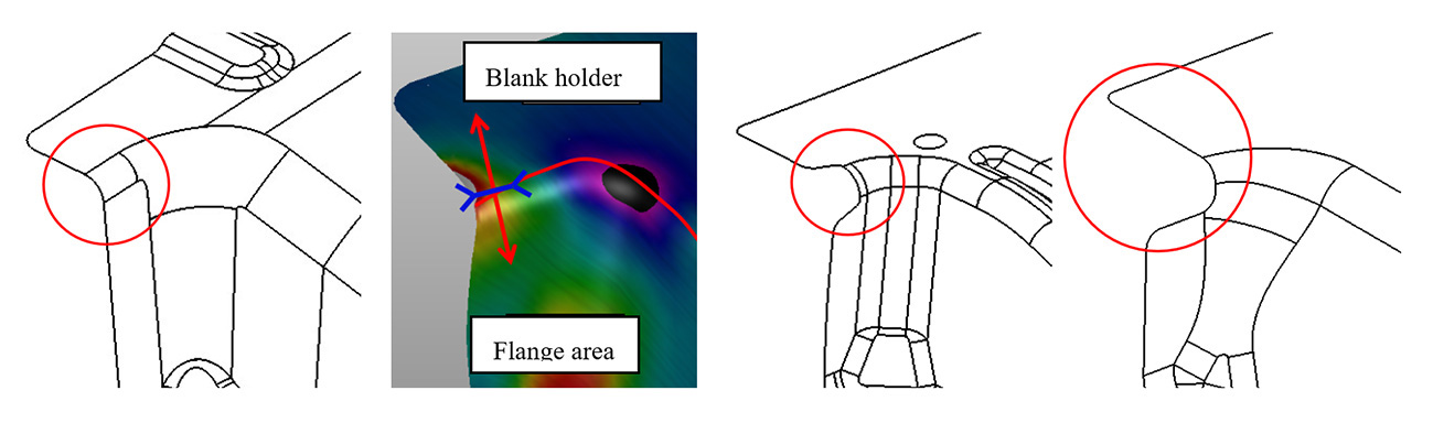
Fig. 7: Defect area and simulation result Fig. 8: Part design optimization
Based on the defect mechanism, the following optimization methods were proposed:
a) Partially shorten or cut the upper corner radius to form an open structure (Fig. 8).
b) Because the upper corner radius is a stress concentration point and the cracking occurs primarily due to tearing at the seam allowance, increasing the corner radius, adding a transition surface, or increasing the side-wall draft angle can reduce deformation severity during forming and help prevent cracking.
c) Apply edge compensation to the radius area to eliminate tearing.
In the edge compensation approach (Fig. 9), the blank size is increased locally at region B during blanking so that the part boundary becomes the forming boundary line f. The maximum position of line f extends 8–10 mm beyond the original product boundary line e.
This reverse blank compensation method effectively eliminates cracking in region B. In subsequent operations, excess material is trimmed according to the original boundary line e. Simulation comparisons in Fig. 10 show that the cracking issue is resolved after applying this compensation strategy.
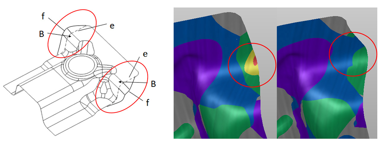
Fig. 9: Partial edge compensation Fig. 10: Comparison of conventional and compensated results
2.3 Wrinkling at Upper Corner Positions
As shown in Fig. 10, the part is formed using a process in which the central area is restrained while both sides are formed freely. Because two side walls with an included angle of approximately 90° are formed simultaneously, and the blank holder does not fully constrain the corner radius region, material accumulates at the intersection of the three surfaces.
The excess material protrudes at the corner during forming and cannot be eliminated after the press closes, resulting in wrinkling.
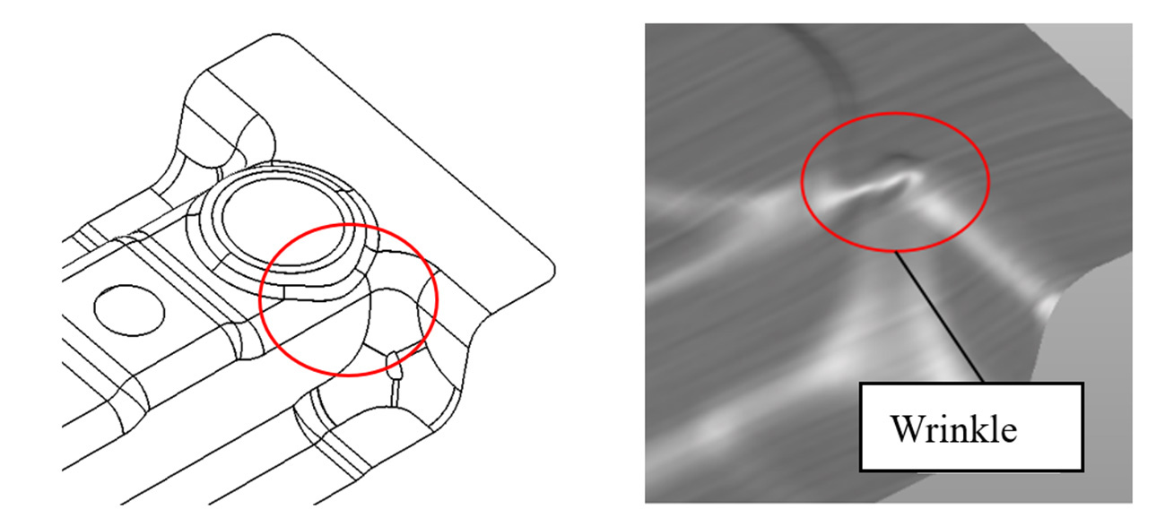
Fig. 10: Product design and forming process simulation result
The main optimization methods include:
a) Adding raised wrinkle-absorbing features at the top corner positions.
b) Introducing transition surfaces to increase the forming angle of the side walls.
c) Increasing the radius of the tooling side walls.
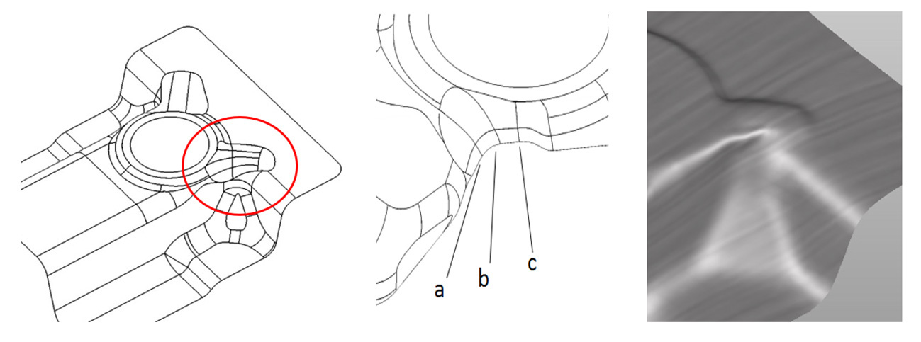
Fig. 11: Simulation results of optimized products and forming process of a certain model
Based on the wrinkle distribution shown in the CAE simulation in Fig. 10, wrinkle-absorbing features were added at the corresponding locations (Fig. 11). The feature follows an arc shape along the length direction. Its top includes a flat section 3–5 mm wide, with smooth chamfer transitions on both sides. The feature extends to the chamfer arc at the end of the vertical side walls.
This flat section helps prevent bending and upward warping of the sheet when the blank holder applies pressure. After optimization, CAE simulations confirmed good forming performance and improved final part quality.
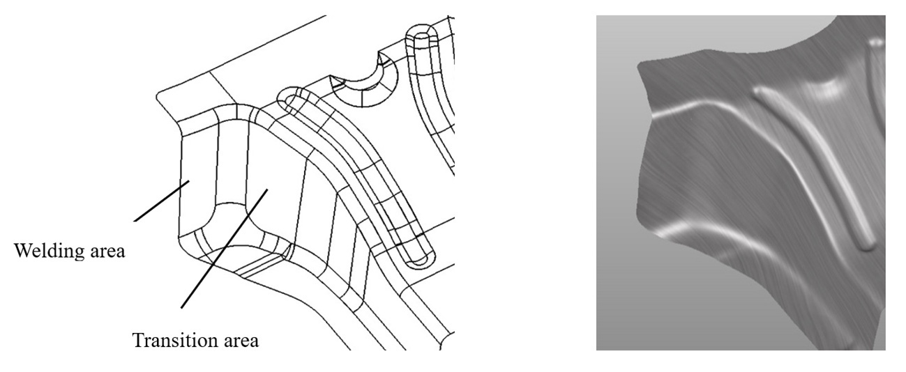
Fig. 12: Combined optimization using schemes b and c
If additional assembly relationships exist on the upper surface, wrinkle-absorbing features may interfere with assembly. In such cases, a combined approach using schemes (b) and (c) can be applied. Transition surfaces are added to the side walls to increase the angle between the side walls and the welding surface of the longitudinal beam. Larger corner radii are also introduced to smooth the flanging transition and reduce wrinkling.
2.4 Flanging Cracking at Lower Concave Positions
As shown in Fig. 13, during downward movement of the die at the lower concave areas on both sides, the intersection of three surfaces contacts the sheet first. This sharp-point geometry continuously rubs against the sheet during forming, while the flanging gap between the vertical walls is relatively small.
As forming proceeds, the sheet experiences increased thinning at the lower concave position, which can cause hidden damage and eventual cracking.
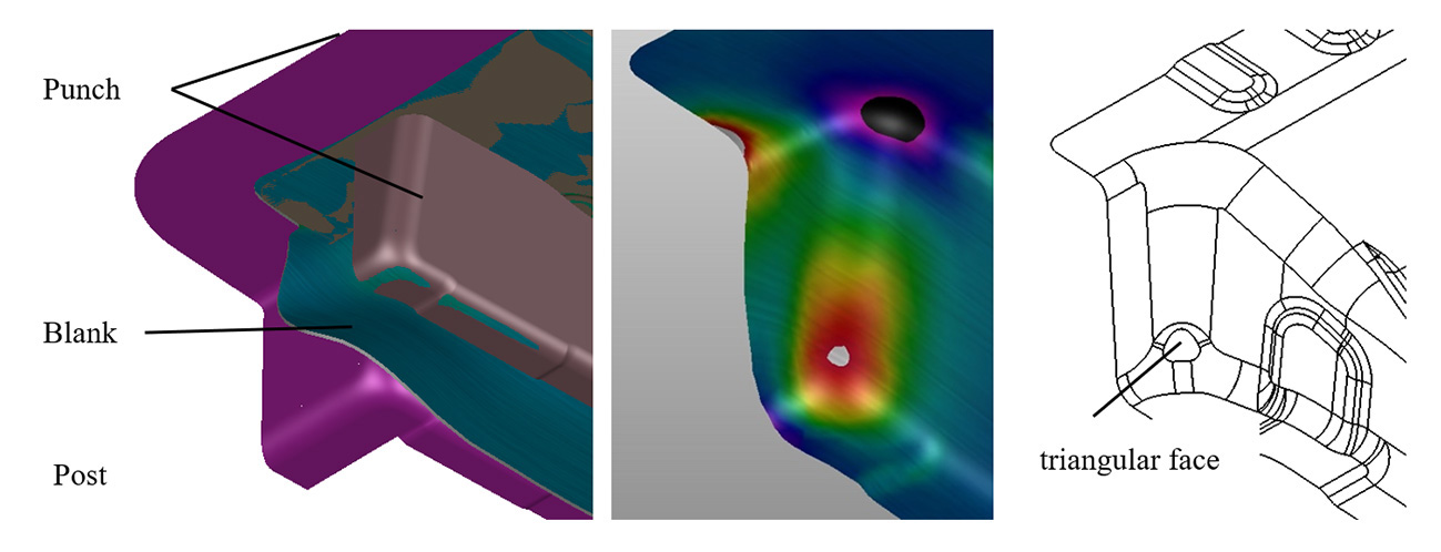
Fig. 13: Defects and optimization for lower concave
This cracking is caused by excessive deformation. Since the flanging punch–die gap typically cannot be adjusted, optimization focuses on reducing the multi-directional tensile force at the intersection point and limiting extension deformation of the blank.
The main measures include:
a) Spheroidizing the lower concave surface or adding triangular features to eliminate sharp-point stress concentrations.
b) Shortening the cross-sectional length at the concave region to reduce deformation.
c) Adding transition surfaces (as in scheme b of Fig. 12) to increase the angle between the welding and transition surfaces, thereby reducing tensile stress during deformation.
These measures help ensure smoother material flow during forming.
3 Conclusion
As automotive safety and chassis performance requirements continue to increase, the design and process optimization of floor crossmembers have become increasingly important.
In this study, AutoForm simulation and process validation were used to analyze stamping behavior at key locations of typical floor crossmember structures. Targeted optimization measures were proposed to address common defects such as cracking and wrinkling. The results provide useful guidance for solving similar forming issues in other automotive structural components.
Thank you Chen Shitao & Ruan Linfan:
R&D of JAC Anhui Jianghuai Automobile Group Co., Ltd.,
Hefei 230601, Anhui, China
References
[1] Jia Gengfeng. Process Optimization Design of Rear Floor Upper Crossbeam Connecting Plate Based on AutoForm[J]. Equipment Manufacturing Technology, 2019, (05):213-217
[2] Gao Bo, Zhang Dongsheng, Ding Yi. Research and Improvement on Fatigue Cracking of Floor Crossbeam Connecting Plate[C]. China Automotive Engineering Society Annual Conference 2014
[3] Jin Gongzhi, Chen Wei, Peng Weihua, et al. Stamping Process Optimization of Automobile Rear Floor Upper Crossbeam[J]. Forging & Stamping Technology, 2019, 44(02):31-36
[4] Cheng Heping, Qin Ying, Ma Jie. A Solution to Flanging Cracking of Front and Rear Floor Connecting Plates[J]. Forging & Stamping, 2023, (22):76-78
[5] Zeng Feng. Structural Improvement of a Connecting Piece of Automobile Rear Floor Crossbeam[J]. Times Automobile, 2022, (06):157-158


?")


