
To Achieve Surface Quality, In-House Saves Time
In this blog post, Ronald Peck from AutoForm USA explains how a local company took on new responsibilities, improved their capability, and shortened their schedule by embracing a new tool in their engineering process, while addressing YOU as the reader to share your approaches to balance surface quality when applying compensation to tools.
Back in the spring of 2019, our process design class had an attendee who was interested in our surfacing module. This individual was the only person currently using CATIA at his facility, and only in a limited capacity because they didn’t have an in-house structure or methodology for this type of surface creation within the program. This step was performed at their parent company overseas after the local office completed the initial work. His team would then wait to receive the completed file. However, with a twelve-hour time zone difference, this delay meant losing half a day or more. In addition, surface creation of this type takes substantial time to complete when modified manually. It became obvious that bringing surface creation skills in house would shorten their lead-time and provide more value for their customers in the future.
Adding more tasks and responsibility normally means more work. However, that was not the case this time around. As the perceived responsible party, the in-house team wanted to know the history of all the changes made — which would in turn make any issues easier to fix and help explain to the customer why certain changes were made. With the speed of our software today, why would anyone not consider bringing more skills in house? The reliance on obtaining information from overseas created a bottleneck and with all the internal back and forth, important points could easily get lost in communication or translation. Further, when dealing with part change requests, it was clearly more efficient for them to do the work themselves and understand the information firsthand. Now, they are dealing with their OEM customer directly and meeting all their requirements. The following paragraphs describe a few of the benefits they observed from implementing AutoForm-ProcessDesignerforCATIA.
During the early implementation of our software, the company encountered an issue with one of the panels that we were benchmarking. This particular panel had been run through several compensation loops to satisfy their dimensional requirements. However, in doing so, the surface quality degraded. There is always a balance of accuracy and surface quality to maintain so the compensation works as desired. The customer showed me the poor surface quality of one of the compensated tools, shown below in Fig 1.
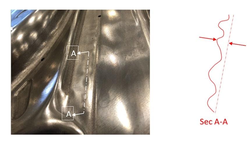
Fig 1: Photo of an actual tool surface. Machined from direct compensation, NOT using AutoForm-ProcessDesignerforCATIA.
To fully explain how our compensation editor successfully improved the quality of the part, I have to “name drop” a few software products here. I had him QuickLink the vector field from their compensated AutoForm Forming file that we were benchmarking into our surfacing module, AutoForm-ProcessDesignerforCATIA. We then applied a basic vector field compensation to this tool. The same surface area now showed a dramatic improvement in quality, as evidenced in the zebra line images below. This comparison could also be performed in more detail using CATIA’s surface analysis tools. However, for simplicity of explanation, we are showing only the zebra result from AutoForm in Fig. 2 and Fig. 3 below.
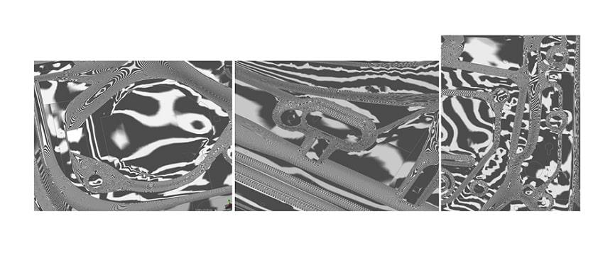
Fig. 2: Zebra lines of compensated surfaces, prior to AutoForm-ProcessDesignerforCATIA
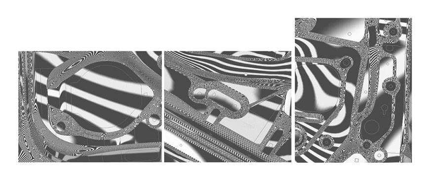
Fig. 3: The zebra lines are now much smoother after applying AutoForm-ProcessDesignerforCATIA
After several product revisions and some tweaks to finalize the developments, the customer was pleased with the results. Then it came time to begin the compensation for these tools. As this was their first time following AutoForm’s complete process model, they returned to us to verify that they were performing all the steps in accordance with our recommendations. We had several meetings to ensure that they were executing the final compensation process correctly after the mentioned product changes.
A key benefit for the customer was that the local office – which was responsible for die build, tryout, and eventually production – could finally execute the compensation themselves, instead of relying upon their overseas headquarters. They could also do this within a relatively short time at a high surface quality that met their requirements.
By reviewing these interesting pictures along with their methodology, they didn’t explore only AutoForm’s process to achieve quality surfaces, but also considered several others. This led to a dialogue comparing various methods — some good, others not so good. Now they’re equipped with additional techniques and software tools for future projects, as well as a renewed approach to their own engineering process.
To conclude, I leave a few open questions for readers to comment:
- How do you balance surface quality with the desired accuracy when applying compensation to tools?
- How do you deal with part design changes after you have already applied compensation to your tools?
- What is your basic compensation workflow after a set of nominal shape design surfaces are created in CAD?
- How much of your time is taken up by compensation work, as a percentage of your engineering hours?


?")


")