
The Infamous Easy Button: Can It All Be Done for You?
We all wish we had one. Managers make jokes about it and employees daydream about it. We’re talking about the infamous Easy Button, to instantly accomplish any task. You could go to your job, hit the button, walk away and cash in your paycheck. Who wouldn’t want that? But the reality is that no matter how advanced technology has become, your job cannot be done with just one click. Maybe certain steps along the line, but not the entire process. Human interaction and knowledge are key to carrying out an effective manufacturing process.
The Struggle to Exchange Project Data Without Errors
Picture this: you’re at the stage in development where the plans are all being finalized and the design has begun. But getting the part geometry and all of the planned and discussed processing together is just a mental hurdle that feels impossible to get over. It may not even be a difficult task, but it’s standing in your way. Perhaps it has already been discussed, maybe even laid out in another CAD system or in another file type. Maybe they were planned in AutoForm, and maybe not. If the general process was simulated to validate the plan and process, then there is a valuable set of data that can be used directly for continued maturation of the process. Whether examining a rough or final concept of the full process, you should not have to look up the tip points, tip angles, or even which process a specific feature is being created in. It should all be stored using correct and orderly naming so everyone can understand the full process.
How departments typically achieve this is by extracting this information with whatever capabilities they have with their simulation software or CAD system. Generally, one will have to open and evaluate the design or simulation to determine the process, what coordinate system(s) and tip(s) were used per station to achieve the proper part orientation, and what features are being formed or trimmed in what station. Sometimes this information is clearly available, but often it takes some investigation to determine. This information is then either written down on either an “old school” piece of paper, which is my preferred method, or a document is created on the computer and the information entered. Now in regards to the tool and part geometry, a lot of time can be spent here extracting and exporting the data. Generally, surfaces are extracted from the solid bodies and individually exported, ideally with a naming convention that others can interpret. So, in an 8-die lineup, depending on the complexity of the part and die requirements, you could have anywhere between 30 to 100 tools, including trim curves, that would be used for simulation. So, you have to spend time ensuring only those tools are displayed, and then going thru the waiting game of watching each translate through, a process we all know too well.
Wouldn’t it be a huge time saver if you could just hit a button and watch the automated process happen in front of you where all of the required information you need is shared and translated out automatically?
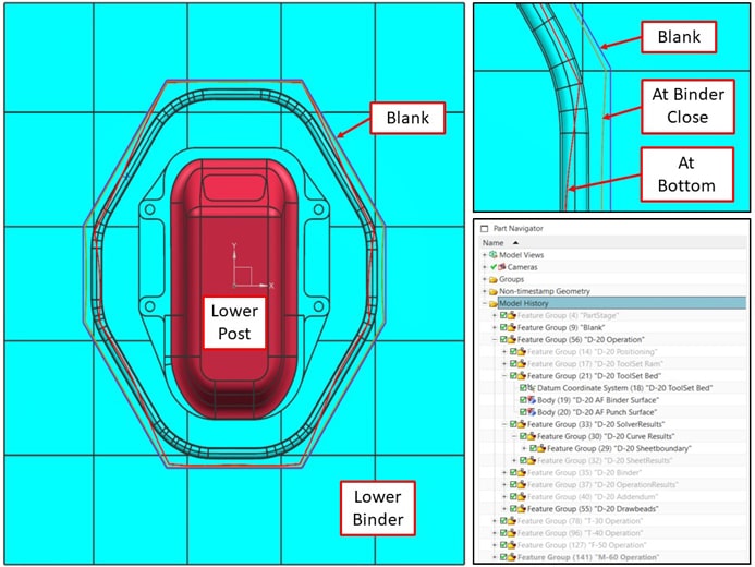
In the image below, you can see an example of the STARTING POINT in NX for a NEW design when reusing the Concept Process that was confirmed during early feasibility with AutoForm.
A General Overview of What is Shared Using AutoForm
AutoForm-QuickLink is the functionality for a bi-directional exchange of data between AutoForm Forming and CAD systems (CATIA and NX) or Management systems (PDM…). It makes use of information and decisions across several platforms and possibly different groups to help pass information and geometry to improve the overall workflow. Basically, it’s a way to link departments together, keeping everyone on the same page. Thus, paving the way for better informed decisions.
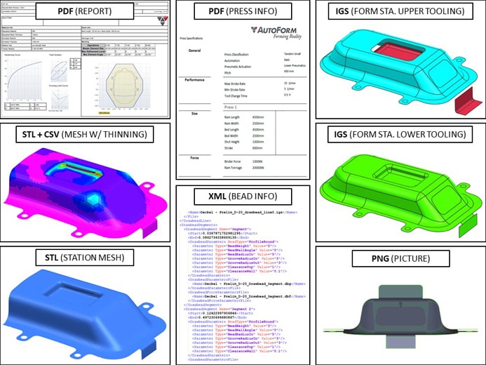
A vast amount of information can be shared out of AutoForm into a single compressed zip file. This exported data can include the concept data geometry such as tool surfaces (die, form and wiper tools), curves (profiles, drawbead lines and material zones) and points (pilots, draw-in, spacer groups, spheres and clamps). In addition, project information like material type and thickness along with process information including the planned operations, positioning, tool direction and press data can be included. There is a long list of items that can all be exported and setup using a standard to suit your company’s needs so you are sharing and receiving exactly what you need. Here is a general list of file formats and possible exported geometries and data:
CSV: Sheet element information.
DBG: Drawbead profile information including the Bead and Groove height, width and radius.
Iges: Part boundaries at end of operations, trimlines, blank outlines, drawbead centerlines, tooling surfaces created using our Die Face module or those that were brought in initially from a CAD software.
PDF: Simulation Report if created in Report Manager.
PNG: Images including Part Geometry Views, Station Parts & Results, Blank Outline and Coil.
STL: Each Operation’s sheet mesh.
TXT: Compensation Data including Vector Fields.
XML: Project Data, links to standards and the original AutoForm design file, drawbead parameters, Cushion Stroke, Material Information and Tooling Costs if setup using our Planning and Bidding Solution (PBS).
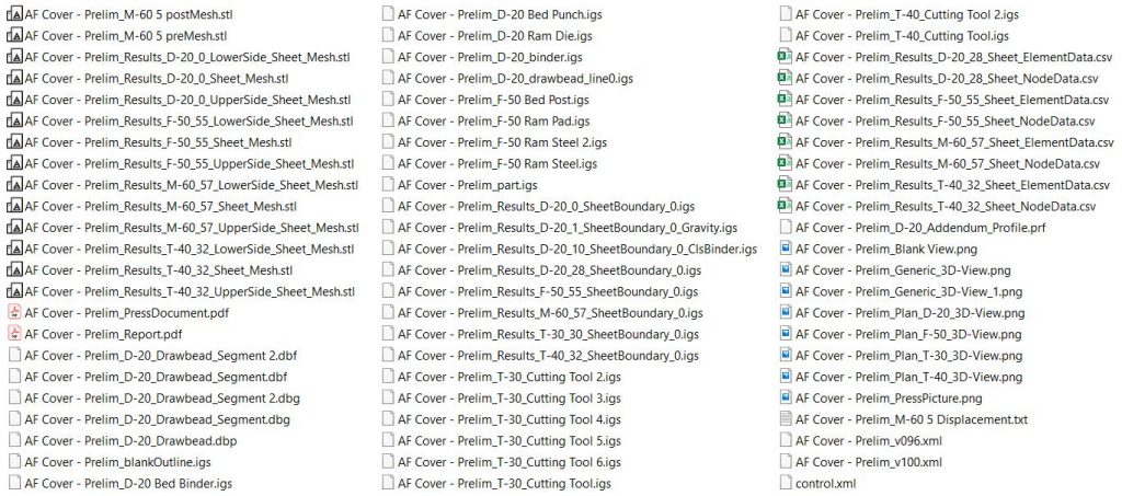
Here is a screenshot of the contents of the Zip file created from AutoForm (some files removed for clarity).
Here is a screenshot of some of the data that has been created when shared in a single package, from department to department, after a full incremental simulation has been run.
A Bi-Directional Workflow Should Be the Industry Standard
Such a solution, as mentioned above, should not only be uni-directional. It should work bi-directionally, utilizing a solution that can exchange data in any form of CAD software. You would then have the ability to import the geometry that was shared out of your forming simulation software via a zip file with just a couple of clicks. This data could then be utilized to further create CAD quality surfaces using NX or CATIA plus AutoForm-ProcessDesignerforCATIA. These geometries would then be shared back out as another QuickLink file, and brought back into simulation for validation in a fraction of the time.
Both AutoForm-QuickLinkforNX and AutoForm-QuickLinkforCatia utilize automatic and consistent naming of imported and exported features (we call it Managed Process Items), resulting in an expedited CAD design process and preventing errors that may occur during manual import and export of operations. It ensures efficient data exchange and improves data consistency, transparency and usability.
So, starting with just one click of AutoForm’s “Share via QuickLink” button, you can begin easily exchanging data, building and finalizing the engineering phase of the part and allowing for multiple departments to communicate without barriers. All the necessary information is available to make educated decisions on the next steps of the process.
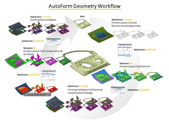
Screenshot of AutoForm’s Geometry Workflow utilizing QuickLink
A while back, I stumbled upon a quote by a man named Dr. M. Eugene Merchant, only to discover that he played an integral part in the manufacturing process, particularly metal cutting. He lived in Cincinnati, not too far from my home in Dayton. His quote illustrates that all the Easy Buttons in the world are still only as good as their operators utilizing the information created from them.
“The technology, and the application of it, as great as it is, will be crippled if you do not also engineer the application of human resources that are to be used in that technology. Only then will technology perform at its full potential.” Dr. M. Eugene Merchant.[1]
Hopefully the Easy Button can help us focus on the more important aspects of our jobs, thus improving the overall process of manufacturing.
Bryan Lang, AutoForm USA.
[1] https://www.automationmag.com/images/stories/LWTech-files/43%20Dr.%20Eugene%20Merchant.pdf


?")


