Series index. Part 1, Part 2, Part 3, Part 4, Part 5, Part 6
What is new about new generation methods?
In fact, tailored tempering is not a novel concept. For over 10 years, different tailored tempering strategies have been used in the field of hot stamping. Some examples include differential cooling, tailored heating, and heated tools. In all of these technologies, it is possible to generate soft zones on the finished part. By changing the temperature and cooling rate of the sheet, it is also possible to control the hardness of the soft zones. However, these conventional methods have a significant drawback: There is a clear delineation along the part separating the hard and soft zones (Figure 1). In other words, there is a line down the part with the fully hardened zone on one side and the soft zone on the other.
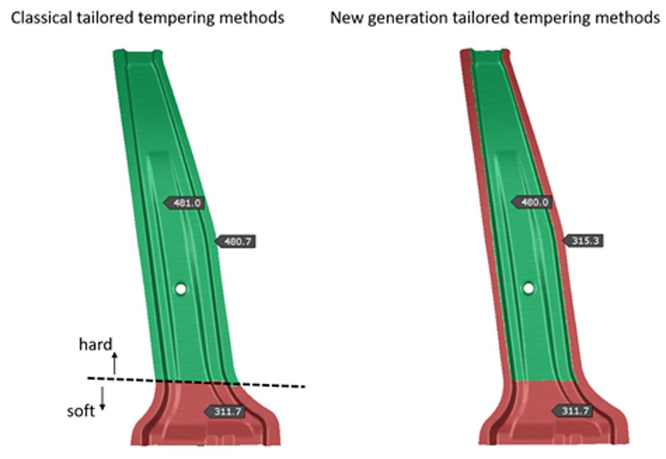
Fig 1. Comparison of parts produced with different tailored tempering methods
The new generation tailored tempering methods directly address this problem by freely distributing the soft zones on the part geometry. They allow us to generate soft flanges around the parts, soft spots in the middle of a part, or larger soft regions to absorb crash energy.
Here are three examples of these new methods:
- TemperBox®: https://www.aptgroup.com/company/news/apt-launching-temperbox%C2%AE-new-cycle-time-neutral-production-solution-enables-tailored
- Thermal Printing: https://schwartz-wba.com/products/tailored-tempering/?lang=en
- PACC: https://www.ebnergroup.cc/en/blog-pacc-module-en
What are the commonalities of these technologies?
In the interest of brevity, we’ll concentrate on the similarities among these new technologies rather than the differences. In every method, the first step is to fully austenitize the sheet. Next, the temperature of the intended soft zones is decreased gradually over a defined duration. Finally, the blanks are transferred to the press. When it comes to forming and quenching, there is no difference compared to conventional direct hot stamping. Consequently, soft zones can be generated with different phase fractions and hardness values. In short, the common feature here is the convectional cooling of some areas on the blank to a desired temperature over a desired timeframe.
How to model these processes
Process engineers will need greater flexibility to correctly define these processes based on:
- subsequent heating/tailoring operations
- different heating/cooling zones with different target temperatures
- the duration of tempering and blank transfers
Regarding the material properties, the temperature history of each zone should be tracked and the corresponding phase transformations calculated, resulting in the final hardness values. The phase transformation and flow curves of the different phases will play a very important role here since the deformation of soft zones will take place under a combination of bainite and ferrite (and maybe even pearlite).
This process is illustrated in Figure 1, which shows the temperature distribution along the process until forming begins. After full austenitization, there is a transfer time of 3 seconds to the next tempering station. There, the tempering takes 30 seconds, during which the temperature decrease gradually to 600°C in the selected zones shown in the figure. Afterwards, there is an additional transfer time between the tailoring station and the press.
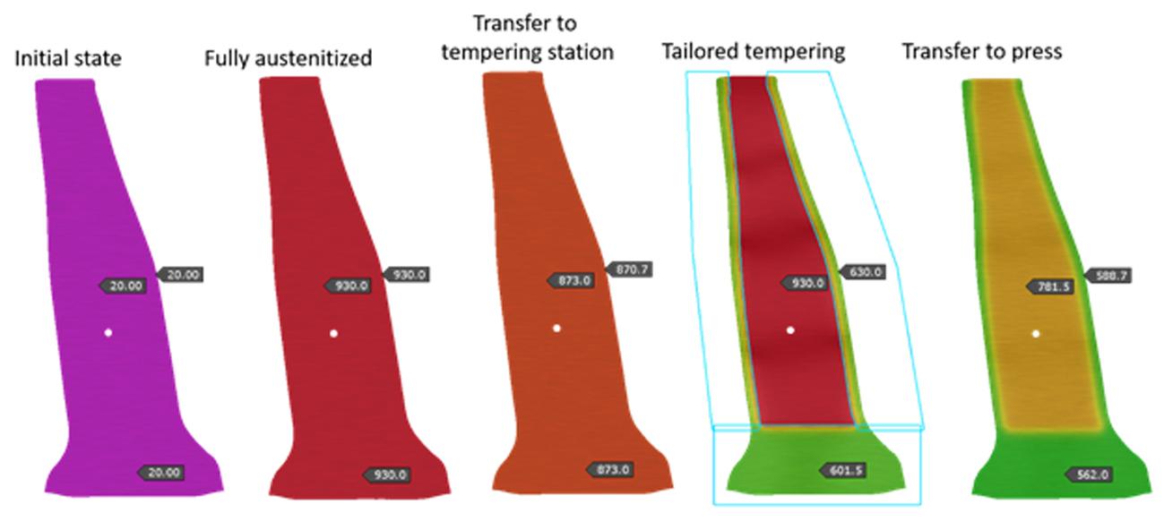
Figure 1: Temperature evolution during tailored tempering
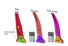
All these steps can be easily defined and the phase transformation is calculated accordingly during the simulation. This is shown in the next figure, reflecting the phase fractions in two different states. Immediately following the tailored tempering station, we see that some bainite and ferrite started to form in the soft zones, where the hard zones are still fully austenite. In the final product, we see that the target hardness of 22MnB5 has been reached. In the soft zones, we can see a mixture of martensite, bainite, and ferrite.
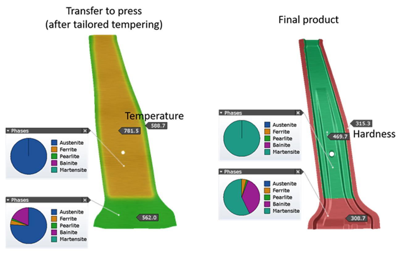
Figure 2: Phase fractions after transfer to the press (left) and after quenching (right)
Altogether, the realistic simulation approach for efficient process engineering supplies valuable input to the BIW engineering workflow. Process engineers will hopefully see the following benefits in their daily work:
- Fast and easy definition of the tailoring process
- Determination of final product properties (hardness, phase fractions, tensile strength)
- Accurate representation of the deformation of soft zones (due to phase dependent flow curves)
- Realistic calculation of the thermal distortions in the part
In part three of our Hot Stamping Challenges series, we covered Heated Tools: Solving the Challenge of Tool Surface Temperature Distribution. In part five we cover Friction and Realistic Tribology.


