
Series index. Part 1, Part 2, Part 3, Part 4, Part 5, Part 6
The use of both cooled and heated segments in a single tool offers the potential to generate different properties in the same part formed from a uniform blank. In this article, we’ll dive into how this works and how a simulation can help to define the process more efficiently. Before getting into the nitty gritty, let’s take a brief look at the rationale behind this approach.
With hot forming processes, the highest possible strength of steel alloys can be reached by generating fully martensitic phases. But beyond that, it’s also possible to generate different zones with distinct properties in a single forming process.
In hot stamping, the initial blank is heated to temperatures above 900°C to generate a fully austenitic phase in the blank. Following, the material is formed and quenched very quickly to obtain a martensitic phase. The rapid cooling rate is critical to prevent other phases with much lower hardness and strength from forming at lower rates — like ferrite, pearlite, and bainite. An overview of the phases produced from different cooling rates is provided by a Continuous Cooling Transformation (CCT) Diagram, shown in Figure 1.
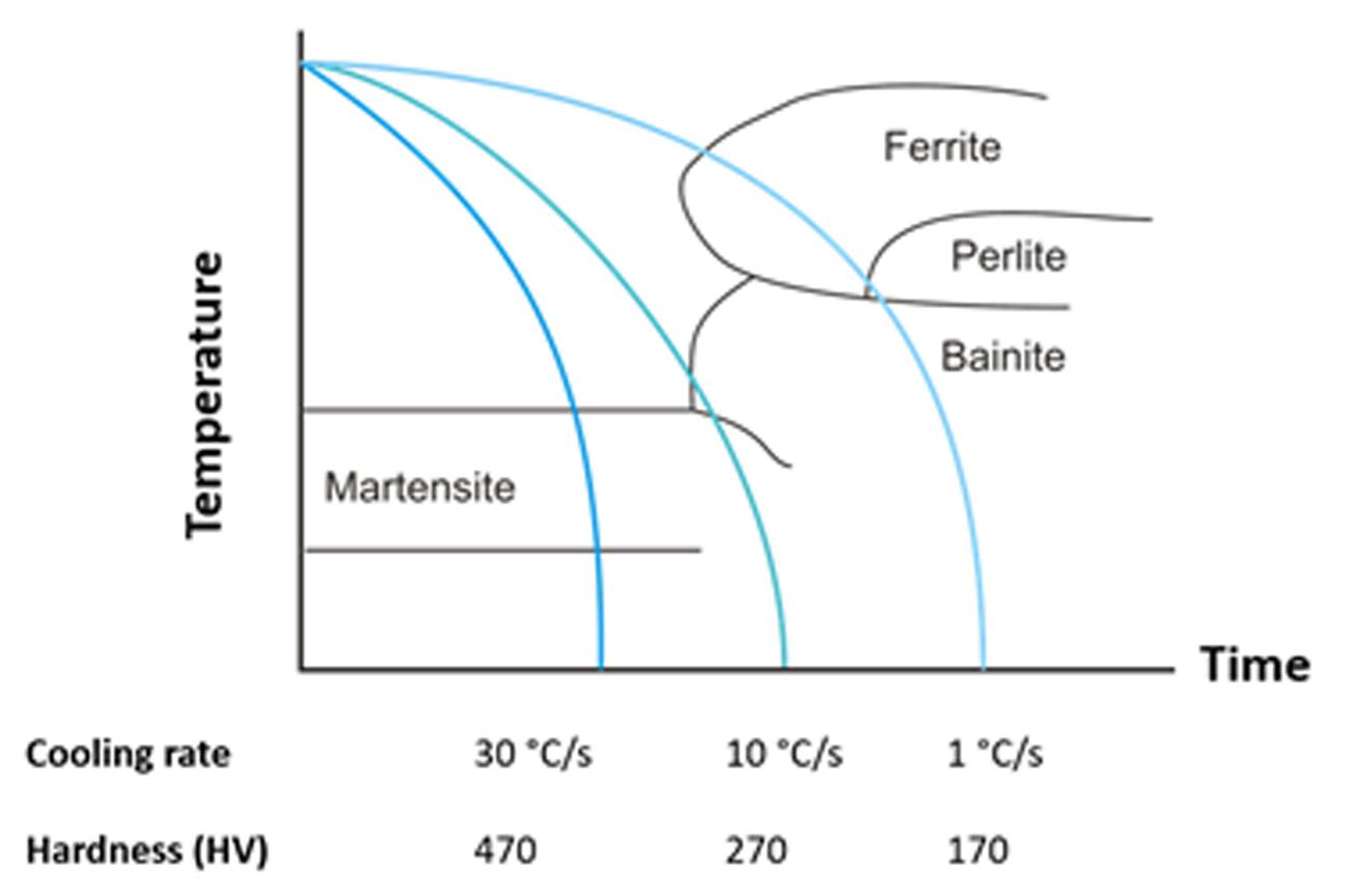
Figure 1 Exemplary CCT Diagram for 22MnB5
As we can see, the cooling rate is the determining factor of the part’s final hardness and strength. There are many approaches to influence the cooling rate, one of which is to use segmented tools with both cooled and heated areas. The main advantage of heated tools is the very narrow transition areas between hard and soft zones and the flexibility when defining the different zones. This approach is therefore suitable for more complex parts.
Finding the right process parameter sets for cooling and heating as well as thermal distortion may pose an issue since the part comes out of the tools with locally varying temperatures. Late changes to existing tools are associated with high costs. Therefore, the engineering phase requires intensive effort to find the optimum parameters for a high quality product while reducing the risk of changes during production. In addition, the process engineering work must be accurate and precise to support predictive engineering.
A common approach is to use models in which the tool segments are defined with constant temperatures (i.e., 80°C for cooled and 300 – 550°C for heated tools). Practice shows that the results obtained with this approach are often sufficient for process engineers. But of course, often means not always. For complex parts with results that are very sensitive to the process parameters, the simplification of constant tool temperatures may not provide results with sufficient accuracy and precision. To increase the accuracy and precision, a realistic analysis with 3D heat conduction must be defined.
To that end, it is possible to define cartridge heaters by their diameter and heating power to perform a 3D heat conduction analysis for the heated segments of the tools. This allows for the consideration of a realistic heat conduction and temperature distribution on the tool surfaces. Like real processes, the tools will warm up with the first parts produced. For this purpose, a cycled simulation is performed, in which the simulation is repeated until a steady state temperature distribution is obtained, representing the real mass production conditions.
With heated tools, we generally have the following additional questions in mind, in contrast to typical direct hot stamping with cooled tools only:
- Do the different hardness zones on the final part fulfill the hardness and tensile strength requirements?
- Do we lose our geometric tolerances due to thermal distortion?
- Are there any hot or cold spots on the tools that may cause hardness problems?
All these questions can be answered before the tools are milled and adaptions can be made accordingly by the process engineers.
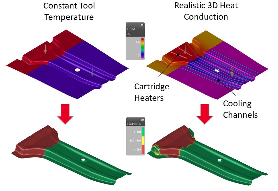
Figure 2: Comparison of temperature distribution and final hardness (Constant temperature vs. 3D heat conduction)
Figure 2 presents the temperature distribution on the tools and its influence on the results, comparing simulations with constant tool temperatures with realistic 3D heat conduction. In the latter case, cooling channels and cartridge heaters with the respective power are defined. The heated tools are slightly cooler on the edges due to poor heating design. This leads to the formation of much harder phases in this area. In a real process, you may consider simply increasing the heating power to overcome the hard phases in the soft zone. But the resulting higher temperatures and temperature gradients may unintentionally change the thermal distortion. Simulations using 3D heat conduction allow us to accurately predict the final temperature distribution on the part, leading to a more accurate representation of the thermal distortions. In this way, process engineers can preemptively compensate thermal distortion by modifying the tool surfaces.
To conclude, the inclusion of heating cartridges in simulations using 3D heat conduction will increase the accuracy of simulation results, especially regarding the final part properties. Moreover, the problems associated with the temperature distribution on the tools can be identified in early engineering phases to eliminate costly modifications on the physical tools.
In part two of our Hot Stamping Challenges series, we covered Simulation Approaches to Super Plastic Forming (SPF) Process. In part four we cover New Generation Tailored Tempering Methods.


?")

