
Traditionally, springback compensation is performed at the very end of the stamping simulation process and is largely based on tribal knowledge. Early work is typically focused on product feasibility, addendum feasibility, and optimization of the beads, blank, and trim lines. Springback is generally considered, but only in a cursory fashion. This yields the natural springback of the panel without accounting for gravity or any other constraints.
Springback compensation can drive changes to the development and in some cases, the product data. When this is performed later in the simulation cycle, timing becomes critical to avoid delays in the tooling as costs elevate very quickly. Changes introduced later in the development are also less likely to fully address the quality issues encountered. This risk can be mitigated early on by taking a more thorough approach to springback evaluation and checking the process window.
Ensure your simulation is using the best material information possible.
Capturing the material accurately is essential to producing an accurate simulation. An inaccurate material definition can lead to under/over-engineering of problems that may not exist in the actual tool. It is always considered best practice to generate a material file from real testing. Early in development, the material is typically not available for testing so alternatives need to be considered, including: a material file tested from the same material used in a different project; properties provided by the material supplier; or properties provided by the OEM.
Meshing and control parameters are appropriate for measuring springback.
When evaluating springback, it’s important to represent both the sheet metal and die face as accurately as possible. Depending on the stage of development and the desired accuracy, several approaches are possible here. However, the AutoForm Final Validation (FV) or Concept Evaluation Plus (CE+) settings ensure that the sheet and tool mesh are compatible, and the proper element type is being used for springback evaluation. There are additional guidelines to ensure the most accurate setup, but within the scope of this article, we are concerned with a very early assessment, which we know will change as the process continues to mature. So for now, we want to focus on a balance of speed, accuracy, and ease of use—not the ultimate goal of 100% accuracy. By investigating such a high-level topic early on, we have a greater understanding of our process potential and can therefore make improvements.
Process the part in simulation to mirror your production plan.
Early simulation work is typically performed before the die design data is available, but you can still build an accurate simulation with good process planning. This will require some collaboration with the team members responsible for process planning, die design, and die tryout.
For the draw die, you need to understand how clearance and binder gaps will be managed in the tool. If spacing is used on the blank holder, it’s best to incorporate a gap-controlled binder, using extra gap as needed to match the planned setup of the tools. If no spacing will be used in die tryout, instead use a force-controlled binder with the appropriate tool stiffness value. This will increase tonnage to keep the tool closed, providing a good starting point for the amount of force required in the tool.
For secondary tooling, it’s difficult to know exactly what these tools will look like before a full die design has been completed. Based on best practices from die design and tryout, you can use AutoForm-DieDesigner to build trim and flange tools that closely represent the final design. An additional consideration is ensuring that tool surfaces that will make contact with the sheet are modeled in simulation to reflect the physical tool. Areas that this may refer to include: 1. Pad contact near break lines and trim lines; 2. Radii that are not forming the sheet, escaped or adjusted before try-out; 3. Shaped regions that will be completely removed from the actual tool as cost savings. All of these elements can be managed to represent a simulation setup and design intent more closely matching the physical die. See figures 1 and 2 (below), which illustrate this idea by removing radii that are not required in the tool because they were formed in a previous operation.
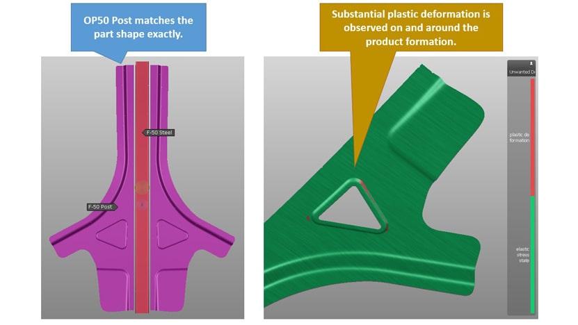
Fig.1: Pad definition inducing unwanted plastic deformation
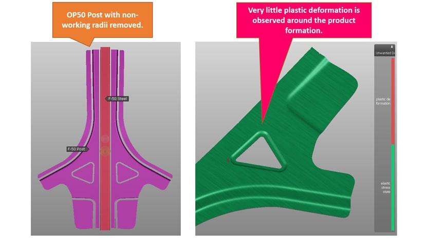
Fig. 2: Re-defined Pad surfaces eliminating unwanted plastic deformation
Another aspect of the secondary operation is specific to the trimming operation. Activating Locating/Gravity, Free Springback at End of Operation, and using Cutting with Tools to all secondary trimming and forming operations is essential to getting the most accurate result possible. Locating with Gravity relaxes the stresses accumulated in previous operations more like real life after removing the sheet from the tool and allows the panel to position itself onto the defined tools. These settings will result in a better representation of a nested panel on your trim post as it will exist in the physical tooling. Using this type of setup will ultimately allow you to see processing concerns earlier and account for them earlier.
Create a green simulation
Once the process is established, you can begin to hone in on building a healthy, green simulation. Before beginning any simulation, run a kinematic check to ensure there are no tool interference issues and that your tool travels are optimized to match typical tryout/production conditions. It’s essential that formability issues (splits, major wrinkling issues, etc.) are resolved before you begin to evaluate springback.
Analyzing springback and measurement setup considerations
Evaluate springback after each operation and utilize draw shell compensation for the subsequent operations as part of your analysis. This allows you to compensate the tools to the incoming panel, ensuring there isn’t any unwanted deformation of the panel caused by pad closure. Doing this in simulation is similar to panel spotting that will take place in the physical tool. Trim optimization should also be considered to ensure that the final panel matches the intended part shape. An accurate trim line will also allow you to optimize the development and blank, leading to potential cost savings.
Utilizing Real Measurement in the springback step will allow you to match the intended measurement fixture based on GD&T or internal best practices. In cases where you may not have the fixture concept or completed GD&T requirements, a Minimum Clamping Concept ensures your analysis is consistent. Following a consistent measurement and compensation plan is recommended to guarantee your compensation is being done the same way every time. Once your company has established best practices on this, you can leverage AutoForm Guidelines to ensure your engineering team is following the recommended protocol for compensation.
With the process and springback measurement established, it’s now time to move to the final step — the robustness check. AutoForm comes with a pre-loaded standard that will automatically set variation for lubricant, blank positioning, blank thickness, and several material properties. Robustness studies offer hundreds of variables with adjustable magnitude, so you’ll need to determine which ones to check for your company. Following the robustness check, you can review the different evaluation results across the spectrum of variation established in the check.
Two of the best tools to evaluate your process for compensation are Cp and Cpk. Cp is used to evaluate the repeatability for your process, while Cpk shows how “centered” your process is to the desired nominal target. These checks are essential to determine if your process is consistent and repeatable enough to compensate for springback. If the Cp proves that the simulation result has high variation, this can lead to major difficulties in compensating the panel. A simulation may not have a good Cpk value, but as long as the Cp proves the process is repeatable, we know that compensation is possible. A visual example of the process capability is shown in Figure 3, where a single point is compared to the overall expected range and relative to the allowable process window.
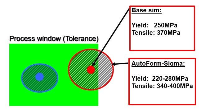
Fig. 3: Process Capability Visualization
To reiterate, mitigate your variance (Cp<1.67) before compensating your geometries. We do not recommend compensating geometries without establishing/demonstrating a repeatable process.
With the stamping simulation optimized, the part can now be safely evaluated for an initial springback check. This early check allows for quick changes to both the product and die face development in reaction to the springback evaluation. Changes are both easier and much cheaper to make earlier in the simulation process, as compared to when the tools have already been machined. As timing becomes tighter and margins become smaller, solving problems early is one way to ensure product launches are smoother, less risky, and subsequently, more profitable.


?")


