Background
In recent years, automotive development and manufacturing cycles have become increasingly shorter, while consumer expectations for vehicle quality have continued to rise. As a result, many OEMs are under increasing pressure to accelerate production, improve quality, and reduce costs.
As a leading new energy vehicle OEM in China, Li Auto aims to reach stable, high-volume production immediately after launch while ensuring high quality from the start.
Assembly Simulation Methodology
The Dimensional Engineering department at Li Auto is responsible for the dimensional accuracy and surface quality of the Body-in-White. During the manufacturing process for new-generation vehicles, the team faces challenges such as short Body-in-White tryout cycles, difficulty coordinating tryout resources, and high tryout costs.
To overcome these challenges, the department introduced a new work methodology and proposed the concept of virtual manufacturing, supported by increasingly powerful simulation analysis methods. Using the simulation capabilities of AutoForm Assembly, the traditional on-site tooling tryout process was transferred into a CAE virtual environment.
With this approach, the tryout plan is first verified in AutoForm Assembly before on-site tooling adjustments are made. This allows engineers to begin preparing tryout plans before the physical parts arrive on-site, reducing time and material consumption while improving the speed and quality of assembly parts.
This new methodology supports Li Auto’s broader goal of reaching stable, high-volume production sooner while maintaining quality from the beginning.
Problem Description
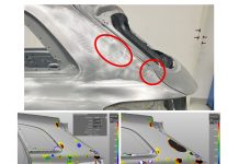
During the development of the hood assembly for a Li Auto vehicle, the Dimensional Engineering department found during the early soft tooling trial production stage that the dimensions of the assembly parts near the windshield area did not meet specifications, as shown in Fig. 1.
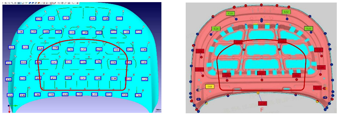
Fig. 1: Hood assembly measurement
The hood assembly was then simulated in AutoForm Assembly, with the results shown in Fig. 2. A comparison between the assembly simulation results and the physical measurement showed that the two were consistent.
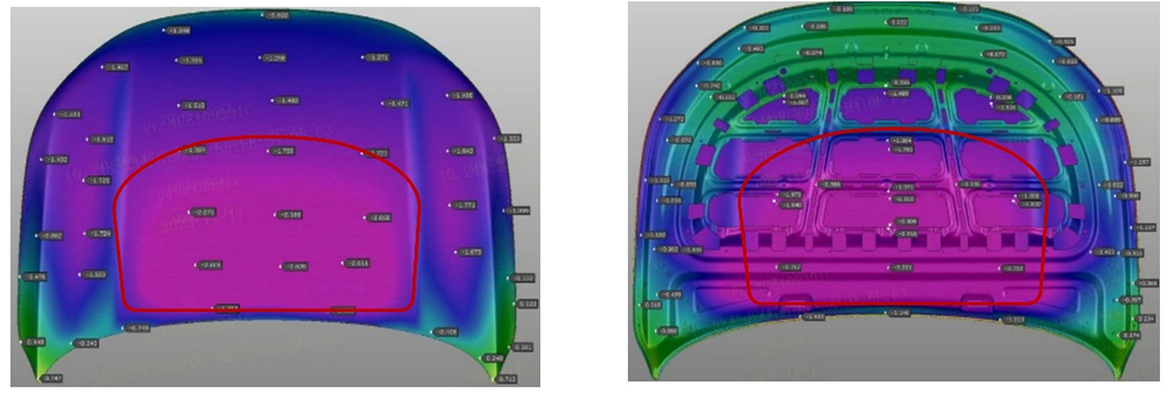
Fig. 2: Hood assembly simulation
Further analysis of the individual part dimensions, including the hood outer panel and hood inner panel, showed that the individual part dimensions were within specification when six support points were used. However, when four support points were used, matching the support condition of the assembly parts, the same out-of-specification behavior appeared in the individual parts. This was especially evident in the hood inner panel, where significant sinkage occurred near the windshield area.
A comparison between the simulation results and physical measurement results, shown in Fig. 3 for the hood outer panel and Fig. 4 for the hood inner panel, confirmed that dimensional sinkage occurred in the problematic areas of the individual parts. This ultimately caused the assembly part dimensions to fall outside the specification.
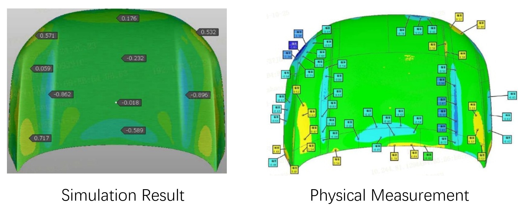
Fig. 3: Hood outer with four supporting points
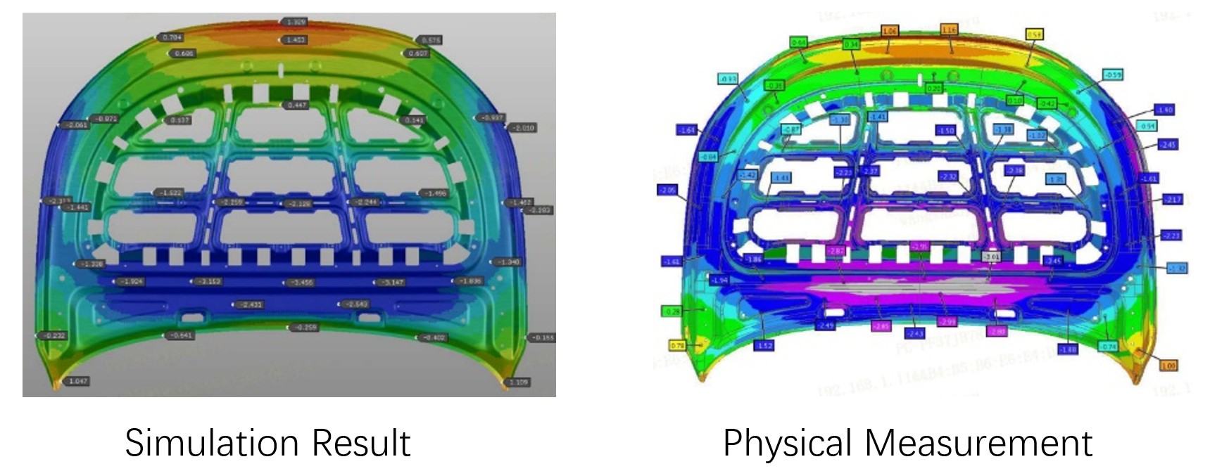
Fig. 4: Hood inner with four supporting points
Assembly Compensation
To obtain qualified assembly parts, it is important to determine the appropriate compensation basis and strategy. Based on the current measurements and simulation results, the dimensional engineers proposed three compensation strategies:
Strategy 1: Compensate the hood inner panel based on the springback magnitudes of the single hood inner panel.
Strategy 2: Compensate the hood inner panel based on the springback magnitudes after hemming of the hood outer panel and hood inner panel.
Strategy 3: Compensate the hood inner panel based on the springback magnitudes after hemming of the hood outer panel and hood inner sub-assembly.
Virtual simulation analysis was performed for each of the three compensation strategies using AutoForm Assembly software. The simulation results were then compared in a matrix format, leading to the identification of the optimal compensation strategy, as shown in Fig. 5.
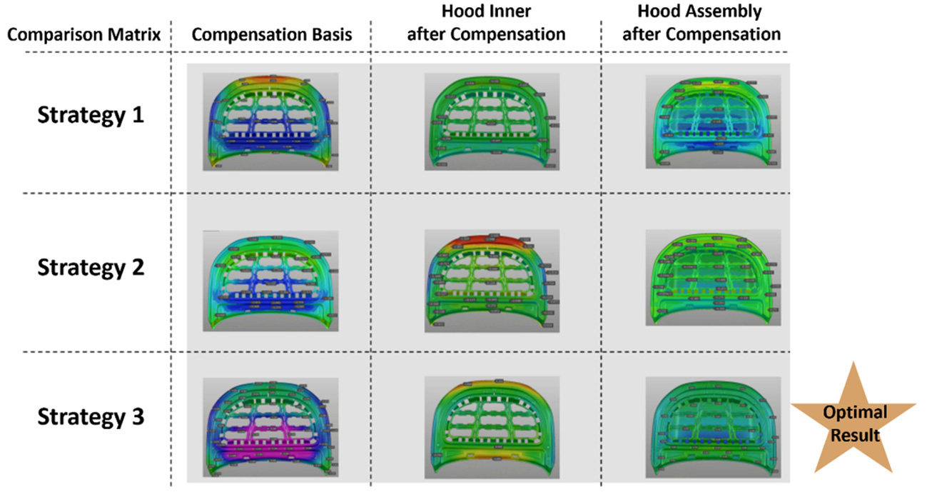
Fig. 5: Simulation results matrix
After the optimal compensation strategy was implemented and optimized through three iterations, the hood assembly dimensions finally met the specifications, as shown in Fig. 6.
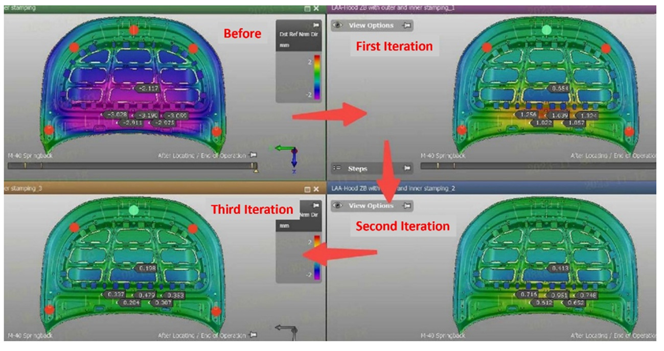
Fig. 6: Compensation iterations
Compensated Surface Validation
The compensation data was exported from AutoForm Assembly, and the hood inner panel was reconstructed in CAD software, as shown in Fig. 7.
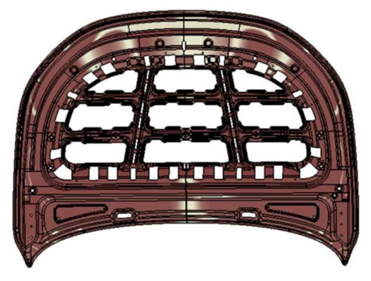
Fig. 7: Reconstructed hood inner
The newly reconstructed hood inner panel was then imported back into AutoForm Forming to perform the single hood inner simulation, preparing for further validation of the final hood assembly dimensional performance. The single hood inner simulation result was then imported into AutoForm Assembly.
The results showed that the simulated hood assembly dimensions were qualified. Ultimately, the physical dimensions of the hood assembly also met the requirements, supporting the goal of achieving a refined vehicle, as shown in Fig. 8.
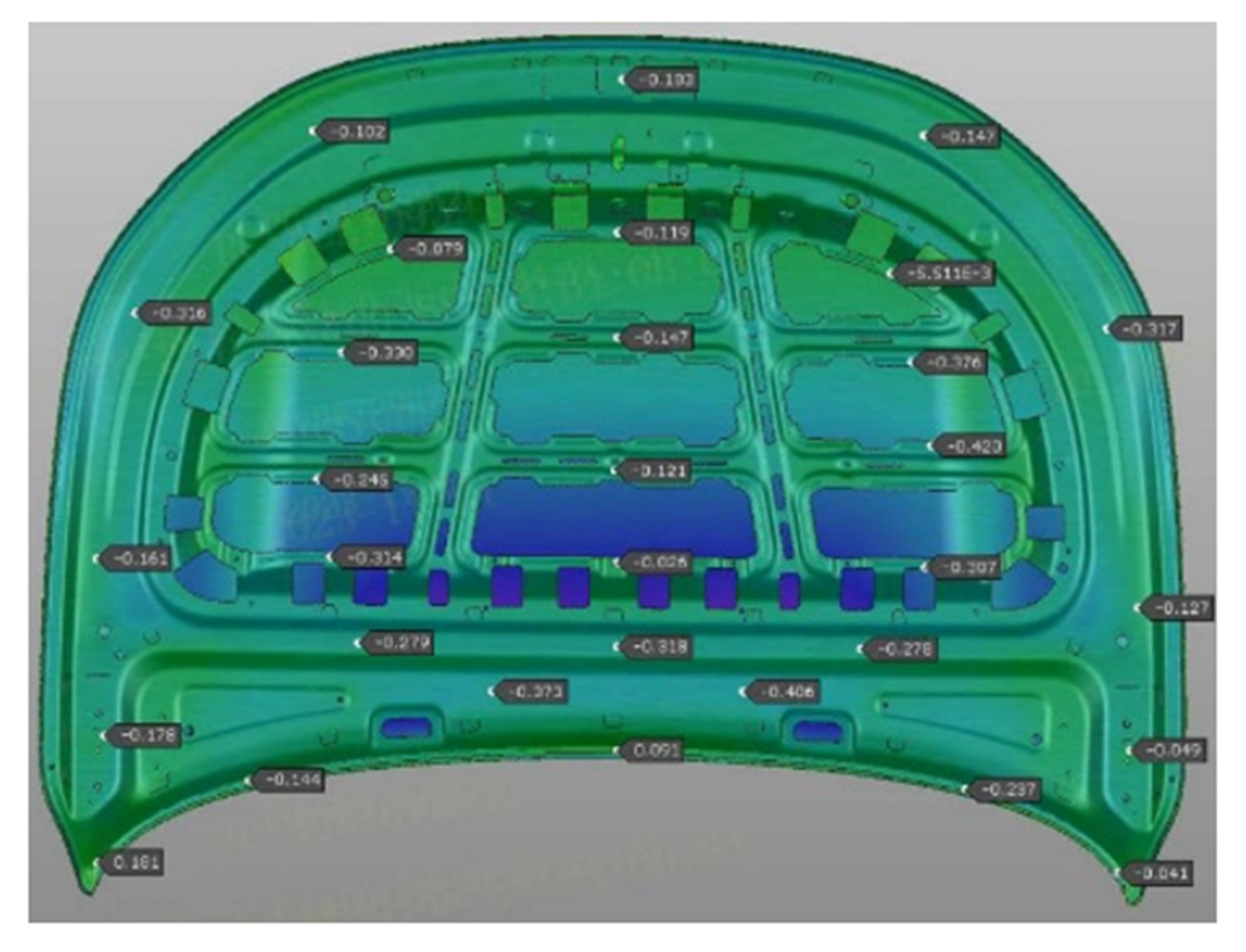
Fig. 8 Qualified Assembly Dimension
Benefits and Summary
By applying AutoForm Assembly, Li Auto eliminated one tryout loop, saving approximately two to three working days. This also reduced the costs associated with two to three sets of tryout parts, engineering hours, and energy consumption, resulting in an overall tryout cost reduction of approximately 20%.
Beyond these measurable savings, AutoForm Assembly provides an efficient methodology for improving product quality, reducing costs, and shortening tryout time. By replacing the traditional experience-based tryout process with a scientific, standardized virtual workflow, the software enables engineers to identify and resolve issues earlier in the development process. This not only improves efficiency but also helps less experienced engineers solve problems more quickly and independently.