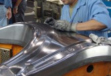
For skin panels, springback compensation is difficult, as it may result in surface defects. Thus, efforts should be made to minimize springback by addressing the process or design itself rather than springback compensation. This philosophy was adopted by Tool and Die Plant, Mahindra & Mahindra Ltd, a reputable tool shop to manufacture automotive skin panel dies in India, for a hood outer panel. They successfully minimized springback in the hood outer from 17mm to less than 2mm without any springback compensation, and during the very first tryout, they achieved a surface accuracy of 85%.
Why forming skin panels is a challenge despite their relatively simple shape
For skin panels, aside from the usual formability issues such as splits and wrinkles, there are two major issues requiring special attention. Firstly, surface defects. Secondly, springback. We refer you to one of our previous articles, in which Yamasei Corporation Japan addressed the issue of surface defects during engineering, thereby saving considerable time and money. Springback is the focus of this article, as conventional methods of springback compensation may not be an ideal solution for skin panels because it could potentially compromise the A-class surface quality, which is not an option for skin panels. Thus, rather than springback compensation, springback minimization should be the first target for skin panels, which requires experience and innovative digital engineering solutions.
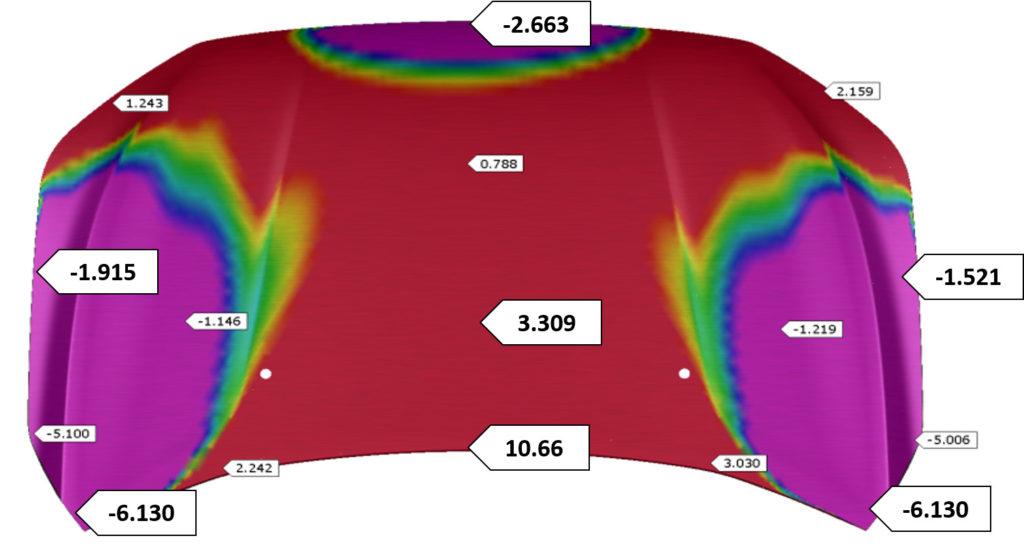
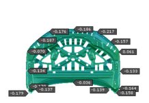
Initial simulations showed that after finalizing the process and draw concept, a springback of 17.0 mm (+10.7mm & -6.3 mm) was observed, which is way outside the acceptable limit. Springback compensation was not possible, as it could affect the surface quality. Therefore, Mahindra decided to minimize springback by addressing the process itself.
Fig. 1: Initial Springback results observed in hood outer based on uniform flange tool entry (click to enlarge)
Based on prior experience, they decided to check the effect of the flange tool entry timing on the final operation, as it may have a significant impact on springback. However, determining the optimum timing is not an easy task through conventional methodologies, so they decided to conduct design of experiments using the AutoForm Systematic Process Improvement (SPI) approach.
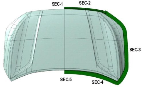
Fig. 2: First, critical sections were identified along the part boundary, where the variation in entry timing could be defined
At each section, a variation of 20mm was defined (10 mm to -10 mm) in tool entry, and the zone between two sections was adjusted automatically. This can easily be defined while creating form tools; considering five different sections, there are many different possibilities and combinations. Finding the optimum solution manually is difficult and time-consuming. However, by adopting AutoForm’s Systematic Process Improvement (SPI) approach, this can be automated whereby the software automatically finds all possible combinations, runs them, and merges the results in a single file — allowing an optimum solution to be found systematically without analyzing each and every file.
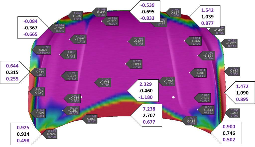
At this point, the first solution was obtained and the optimum entry time for each section was estimated easily, resulting in a springback range as low as 3mm.
Fig. 3: Optimum springback results obtained through the design of experiments using AutoForm SPI (click to enlarge)

Fig. 4: Optimized variable flange tool entry in one of the areas
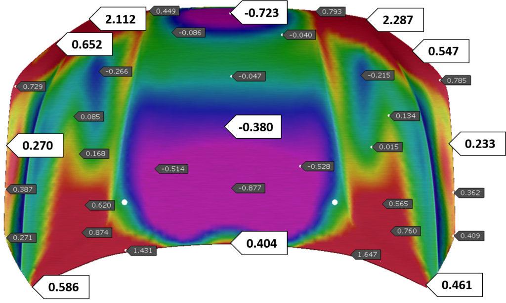
Fig. 5: The flanging tools were further adjusted considering the practical limitations, and springback results were obtained within 1.5mm (click to enlarge)
In this way, Mahindra reduced springback from 17mm to 1.5mm without any compensation, thus concurrently ensuring good surface quality.
Results:
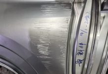
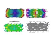
In the first tryout, Mahindra’s team was able to achieve 85% surface accuracy without applying any springback compensation in the draw tool, which was a huge success for the entire team.
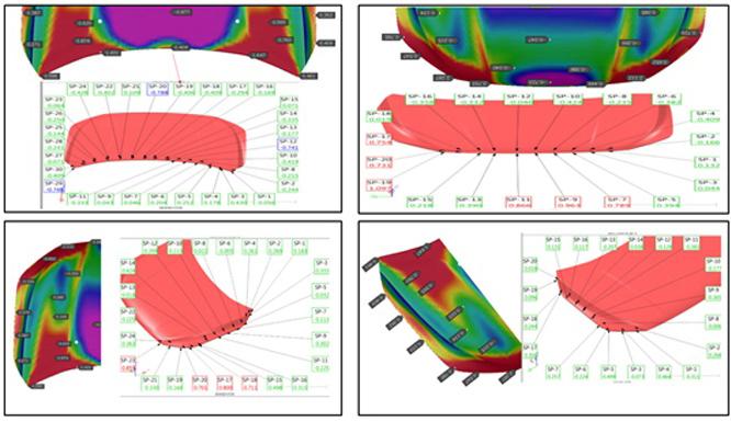
Fig. 6: Tryout results (bottom right) were found to be in good correlation with the simulation results
In tryout, Mahindra could use the innovative solution provided by the Digital Process Model and build it in reality to successfully control the springback in a skin panel — which otherwise would have been very difficult and time consuming. In doing so, they benefitted from significant cost savings, as no correction loops were required during tryout. In addition, die quality improved as no further correction was required to enhance dimensional accuracy of the hood outer panel, and there was a reduction in lead-time. Based on the success of this case study, Mahindra created new simulation standards to implement this approach to all similar parts.
Mahindra – Tool & Die Plant is a reputable die shop located in the beautiful city of Nashik, India, specializing in manufacturing stamping tools for all types of panels (A-class, B-class, HSS-UHSS, etc.). They have been using AutoForm for more than a decade to conduct feasibility analyses. The case study to minimize springback in a hood outer panel without compensation was initiated by Mr. Mukesh Thakur, an expert Stamping Engineer and Team Leader.
Thanks to Mr. Mukesh for sharing this interesting case study with the audience of Formingworld.com.


