
It’s Vital and Yet Often Ignored – Here is Why You Need to Look Again!
In this blog post Dr. Eren Billur, leading hot stamping expert and Technical Manager of Billur Makine and Billur Metal Form describes the manifestations of “Force and Energy” at work on press lines as part one of this blog post series. In this part he outlines the risk of damaging a press and describes how to correctly determine the capacity of your press for best use. In part two his post will cover “Calculations for Transfer and Progressive Dies”.
Part One: Forces and Energy at the Press
A mechanical press or a press line, whether it is a tandem, transfer or progressive; flywheel or servo, is one of the largest capital expenditures of a stamping company. Quite often a press is classified and named “only” after its “nominal force” capacity. For example, you may hear that new investment plans include an “800 ton press”. When further details of “press capacity” are then discussed most will first question its bolster dimensions, shut-height[1] and stroke. Although, all of these factors show some capacities and capabilities of a press, and are necessary, these may not be sufficient to determine whether or not a die set can be run under a certain press.
Still today, it is common in stamping plants that engineers limit their selection by merely checking to see if the die fits into the press bed and if the required force of the die (tonnage) is below the nominal force (tonnage) of the press. When other details such as tonnage curve, energy capacity, off-center load capacity, reverse tonnage are not taken into account, a press could be overloaded or damaged very easily.
As Prof. Taylan Altan put it, “A process engineer should have knowledge about the capabilities of a forming machine, so that they can:
1) Use existing machinery more efficiently.
2) Define with accuracy the existing plant capacity.
3) Better communicate with the machine builder.
4) If necessary, develop in-house proprietary machines and processes not available in the machine-tool market.”[2]
Through our customers, we have seen many cases where the capacity of a press is overloaded for long periods of time. Although, the dies seem to work properly – over time, the press body and/or its drive system can be damaged significantly. Another common mistake is to overinvest and under-use a press. In the long run, this may still be better than overloading the press as the maintenance and refurbishing costs are lower. However, the initial investment would be unnecessarily high. Thus, both cases should be avoided.
In order not to overload or under-use a press, the capacity of the press has to be clearly determined. To begin with, a forming engineer has to understand the “rated tonnage point” concept. All mechanical presses theoretically can apply infinite force. When we name an 800 ton[3] press, what we refer to is called nominal force or rated tonnage. All presses apply their “rated tonnage” at a certain point before bottom dead center (BDC). Based on the rated tonnage point, stroke length and the press type (crank, link-motion or knuckle-joint), a tonnage curve can be calculated. Figure 1 shows, tonnage curves of two 800 ton presses, both having 400 mm stroke length: (a) with 12 mm rated tonnage point, and (b) with 6 mm rated tonnage point.
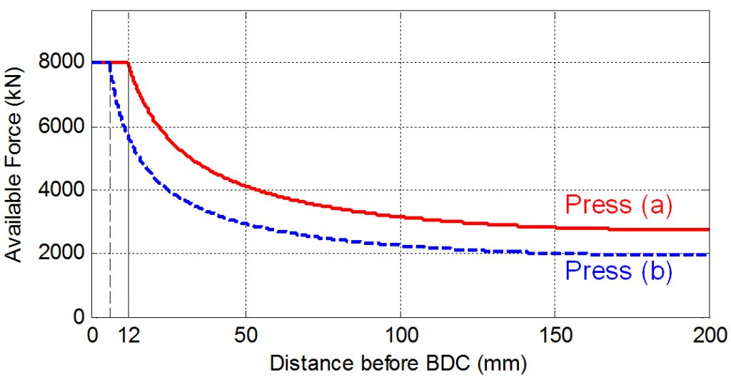
Figure 1 – Comparison of load-stroke curve of two 800 ton presses with different rated tonnage points (both presses have simple crank drive and 400 mm stroke).
It is possible that a die-set which may be used in Press (a) cannot be formed in Press (b). This is easy to explain as typically a press with higher rated tonnage point has more massive connecting rods, columns, etc. In addition, most probably Press (a) would be more expensive than Press (b).
However, what could be more confusing for most is case 2. Here, press (a) is the same 800T press that has a 12 mm rated tonnage point. Press (c) is a 1000 ton press with 6 mm rated tonnage point. As seen in Figure 2, Press (a) has more available force at any given point of the stroke until about 8 mm before BDC. Only in the last 8 mm before BDC, Press (c) has higher available force as the overload protection is set to 1000 ton instead of 800 ton. Now, what does this mean in practice?
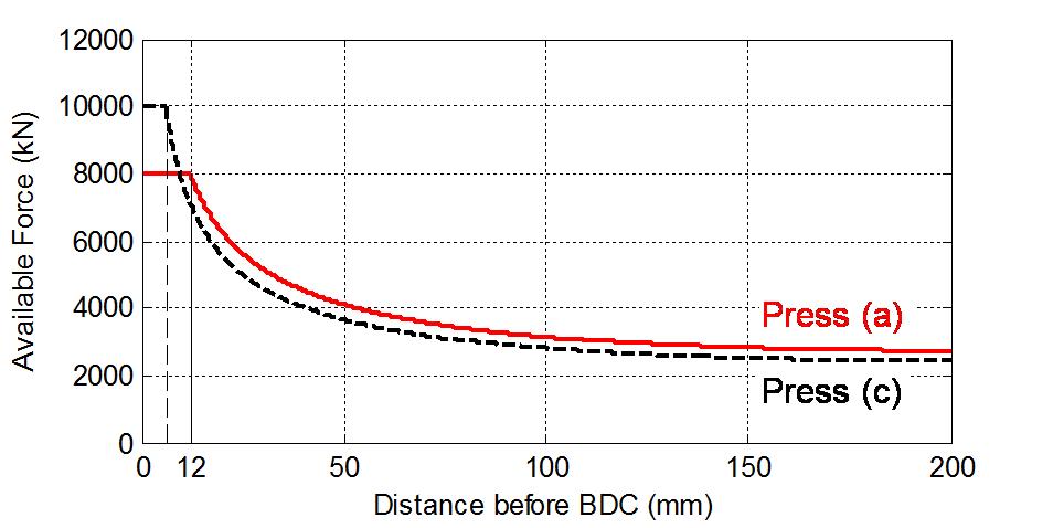
Figure 2 – Load-stroke curves of an 800 ton press with 12 mm rated tonnage point and a 1000 ton press with 6 mm rated tonnage point (both presses have simple crank drive and 400 mm stroke).
At a case study, a reinforcement bracket was simulated. The part is stamped from 2.2 mm thick ultra-high-strength steel. The die-set requires approximately 125 tons hydraulic cushion (blankholder) force. The maximum force required was only 548 tons. Theoretically all 3 presses (a, b and c) should have had enough force to make this part. However, as seen in Figure 3, only Press (a) could stamp this part. What’s important to notice in this example is that an 800 ton press (Press a) could make the part, whereas a 1000 ton press (Press c) could not.
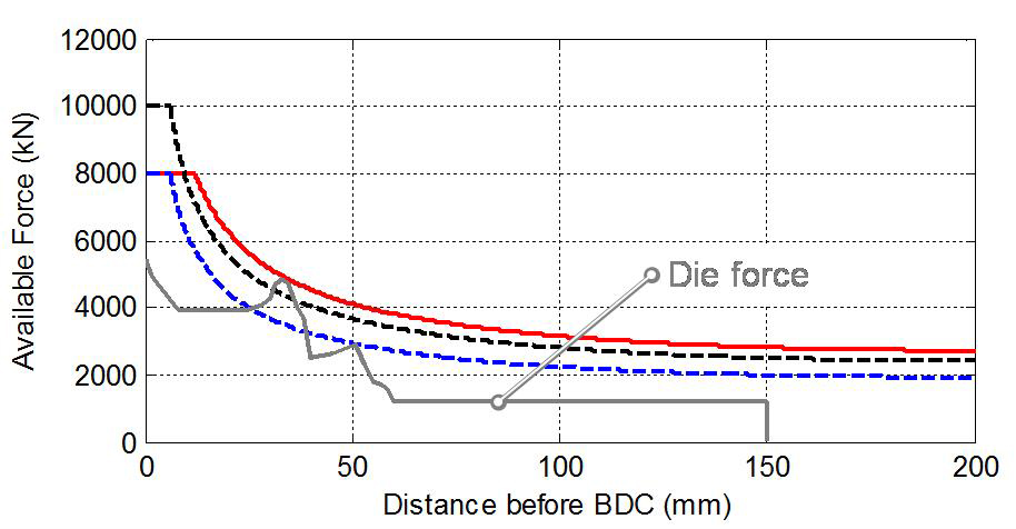
Figure 3 – Case study of a thick bracket. Based on the die force requirement, the part cannot beformed with the 800 ton Press (b) and 1000 ton Press (c). However, it can be formed with the 800 ton Press (a).
It is very common in the stamping industry for engineers to ask “How come this 1000 ton press cannot make the part, but this 800 ton press can?” We have already discovered one potential answer. The second possibility is the energy requirement. This is also often overlooked. Energy is simply force multiplied by distance. However, when the force is not constant, it becomes the integral of force-stroke curve. To visualize this, energy requirement of a die is the area under the die force-stroke curve, as shown in Figure 4.
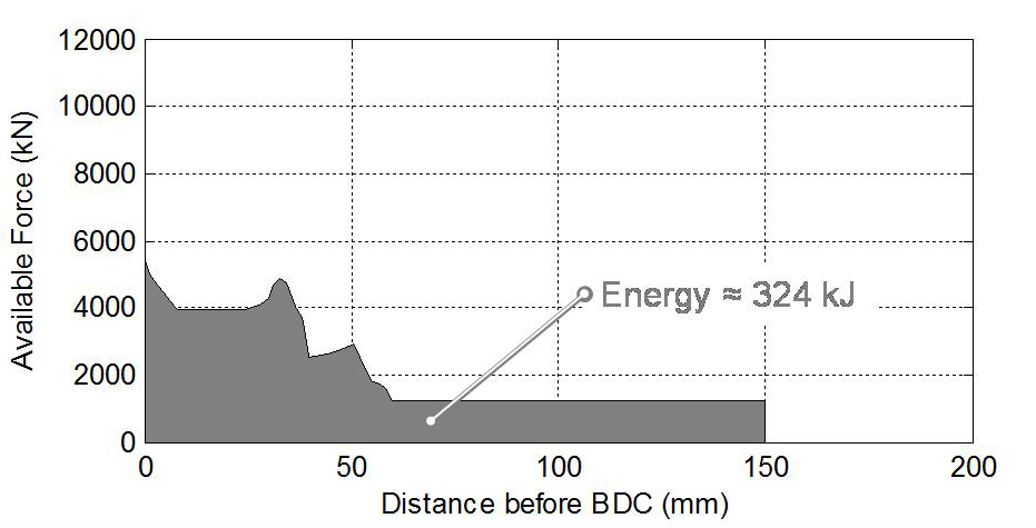
Figure 4 – Energy requirement of the bracket.
Most presses today have a frequency inverter to set the press speed. When the motor speed is reduced, both the flywheel speed and the slide speed are reduced. Slide speed reduction may be required to:
- Improve lubrication in deep drawing purposes,
- Protect die components such as springs, cams, etc,
- Catch up with material transfer or other automation.
In mechanical presses, however, when the flywheel speed is reduced, the energy per stroke is reduced drastically. Figure 5 shows a fictitious but very realistic 800 ton press energy-curve at continuous run between 10 and 20 strokes per minute (SPM). After 14 SPM, the energy available per stroke becomes constant due to motor capacity. If further energy is required, such as in Figure 4, then the press should be operated in single stroke mode. In this case, the maximum possible clutch activation per minute is another input to be known. To produce the bracket in Figure 4, the press has to be set at its highest speed (20 SPM) and should be run in single stroke mode at a maximum of 10 CPM (clutches per minute).
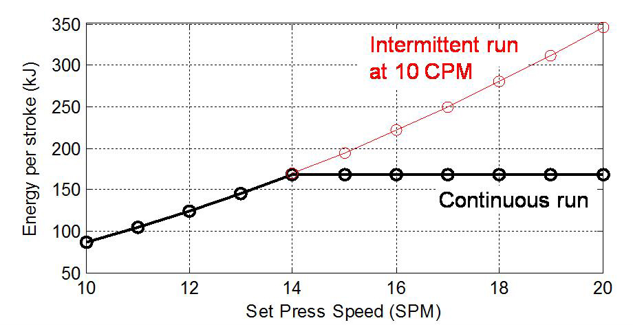
Figure 5 – A sample energy-speed curve for a fictitious 800T mechanical Press (a).
Knowing these factors in detail allows tool shops and OEMs to invest in exactly the right presses, meeting the required capacity exactly as they need without having to waste money on repairing damaged machinery while also avoiding the occurrence of overspending on machinery that was never required.
When a new investment is to be done, and if all the die-sets that will work under this press is known; the best option is to keep force-stroke curves and energy per stroke at given speeds in mind. Thus, overspending or overloading could be avoided; and successful parts per minute could be optimized.
At Billur Metal Form, we are developing software to help you with:
- Analyzing the force and energy curves for die-sets.
- Calculating and digitizing press capacities at your press shop.
- Selecting presses based on these calculations.
For further information, you can contact the author, Dr. Eren Billur at eren@billur.com.tr
Stay tuned for Part 2, where we shall discuss off-center loads in transfer and progressive dies.
[1] Shutheight is the distance between slide and bolster when the slide is at the bottom dead center and the slide adjustment screw is in its uppermost position. It is one of the most important press capacity, as it shows how high a die can be used. Lower dies may be used with slide adjustment or additional blocks of steel to increase its height.
[2] Altan and Tekkaya 2012.
[3] In this text, 1 ton refers to 1 metric ton, approximately 2205 lb-force, 1.1 short ton.


?")

 Technology")
