

Case study of reduced man-hour using AutoForm R10’s new function ‘Die Spotting’
Yean has been making great efforts to build a Digital Process Twin in the tool manufacturing process by replicating (as much as possible) what has been simulated within AutoForm.
Although there have been cases of reducing man-hour by modeling the pressure on the sheet by using AutoForm’s “Contact Distance” results and then transfer it to the surfaces in Process Designer for Catia,” they had to model Die Spotting based on their experience. This was every time consuming process. At the time, when they were struggling with these issues, AutoForm released the newest version which contained a dedicated “Die Spotting,” feature. Feature like this was so needed that it was immediately applied to the tool manufacturing process in collaboration with AutoForm Korea.
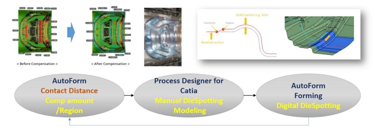
Fig. 1: Yean’s original Die Spotting Digital Workflow Process
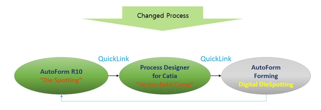
Fig. 2: New Die Spotting Digital Workflow Process
(AutoForm R10 Die Spotting)
Ye-An’s AutoForm R10 “Die Spotting” Use Case (Sheet metal Type – 2 Blank / 2 Part / 2 Out)
Let’s have a look at the Die Spotting compensation case for the Middle part. Figure 3 shows the result of the amount of the Die Spotting by checking the Upper and Lower of the Contact Distance in the AutoForm Forming Evaluation. Through this result, it is necessary to confirm which part of Die Spotting should be applied.
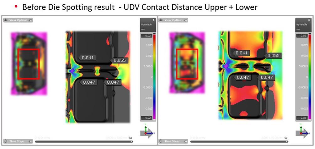
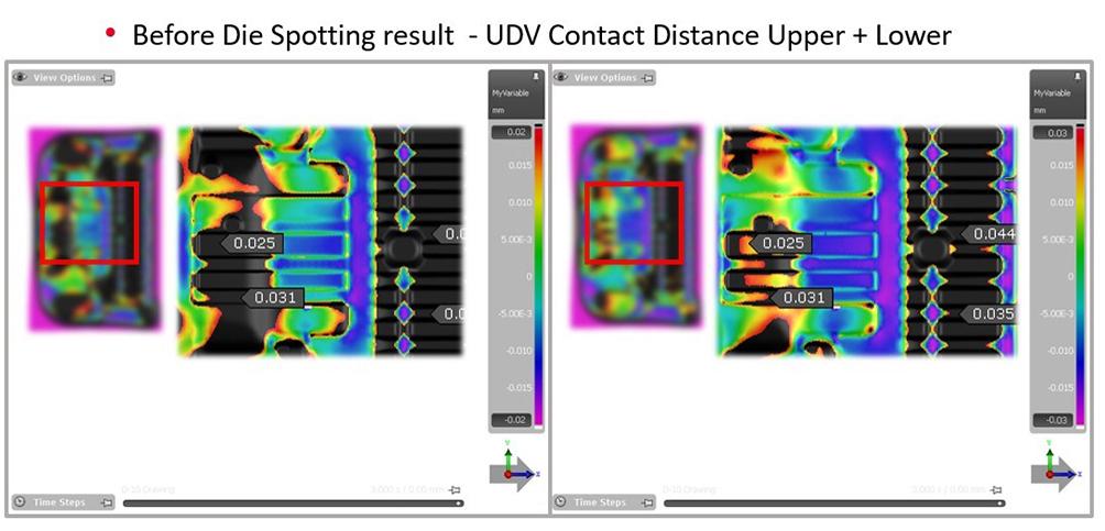
Fig. 3. Checking Die Spotting amount of “Upper + Lower of Contact Distance”
In AutoForm R10 Die Spotting, it is possible to apply Die Spotting Compensation by selecting Upper Die or Lower Die from the desired process tool considering Thinning and Thickening in the simulation result. Figure 4 shows the same amount of Die Spotting Compensation as Figure 3.
After completing springback compensation, our die spotting function can be applied.
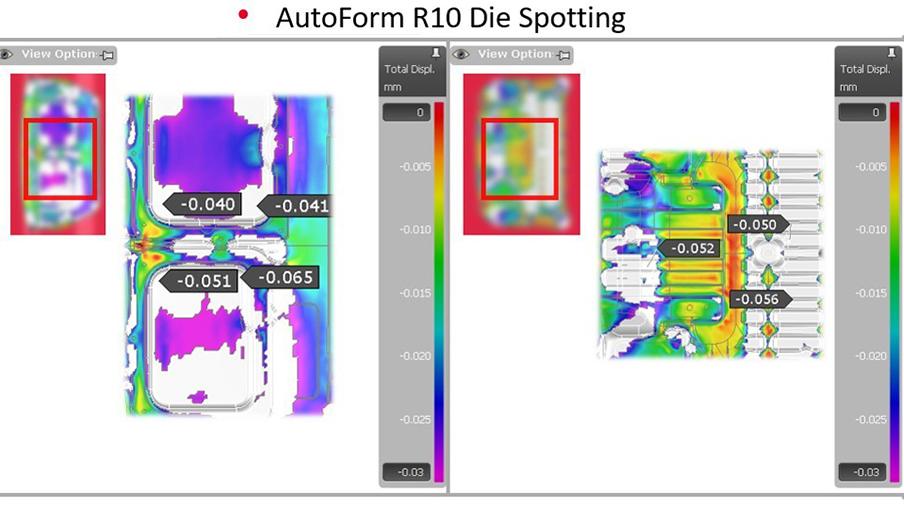
Fig. 4. (Left) Before spotting (Right) After spotting results
After Die Spotting, a dedicated module from AutoForm was used to transfer the Die Spotting information information to Catia, and our “Vector field Compensation” function can be used to make the final Die Spotting modeling applicable to NC modeling. Also if the engineer wants to add the amount of Die Spotting, one can add it by using Process Designerfor Catia “Relief Editor”. Figure 5 shows the completed Die Spotting modeling by adding Relief Editor to the area desired by the tool shop worker after Vector field Compensation.
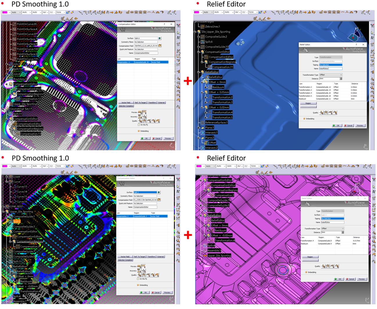
Figure 5. Die spotting Calibration Result of Process Designer for Catia
After Die Spotting Compensation, it is possible to check the surface quality in AutoForm Process Designerfor Catia. Also surface quality can be checked in advance after NC processing. Even if the Die Spotting Compensation amount is reduced as much as the material t is reduced, Figure 6 shows the same Die Spotting result as the existing surface quality. Figure 7 shows an actual tool, and this quality is judged sufficiently applicable to NC operation for the Inner Part.
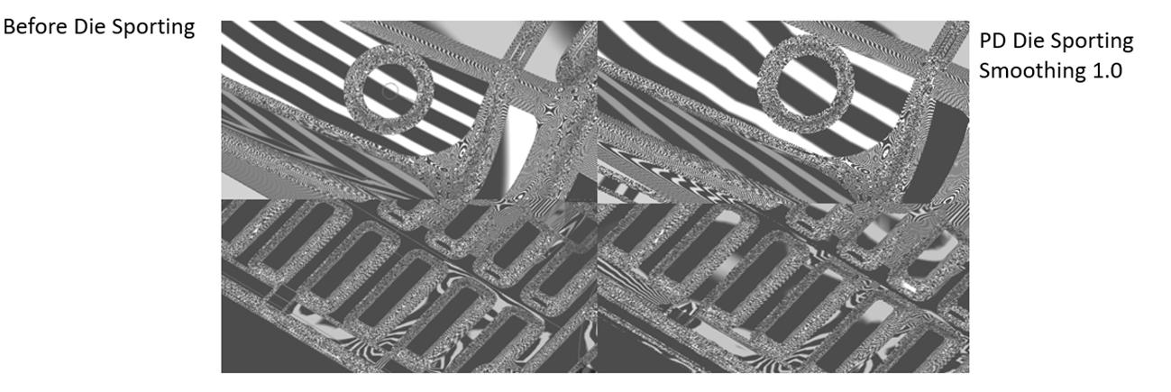
Figure 6. Die spotting Face quality check by using Process Designer for Catia
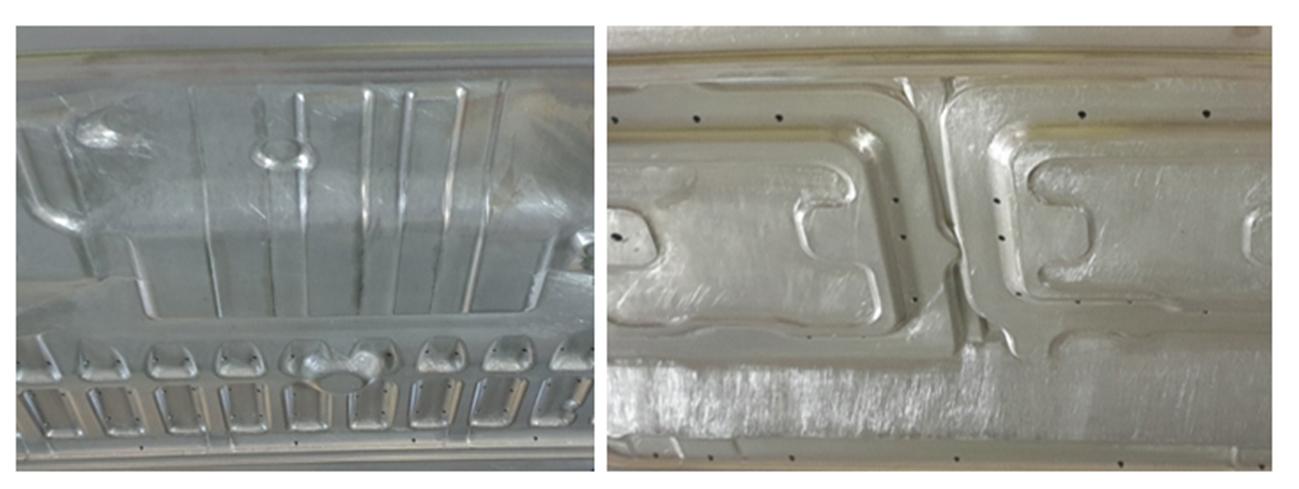
Figure 7. Surface quality in the NC machining of the physical tool
When Die Spotting modeling is completed in AutoForm, analysis verification is performed to check the results before and after Die Spotting. After Die Spotting, it is possible to check the additional area where the die spotting will be applied, and add Die Spotting area by using our “Relief Editor”.
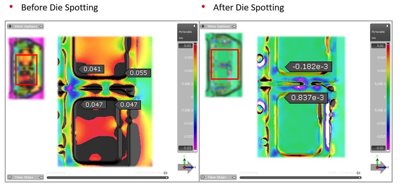
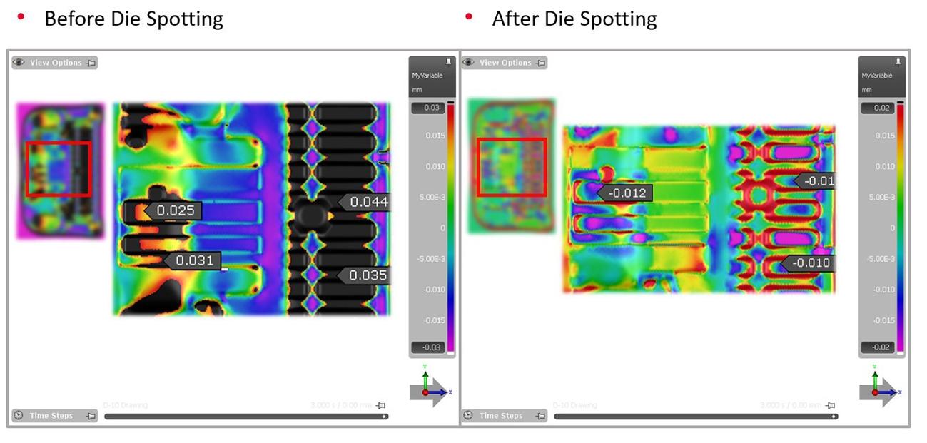
Figure 8. Checking the surface quality in NC machining of the physical tool
The following is the result of the Die Spotting tryout. Figure 9 shows the sheet metal and 1st Tryout’s Die Spotting. Sheet metal in Fig 9 is supposed to simulate 2 parts at the same time. Due to the large size of the sheet, it took time to work in the press shop to eliminate the bending of the press. But in the 1st Die Spotting Tryout, it was reduced by about 50% compared to current Man Hour in Figure 10. In addition, about 90% of man-hour was reduced in Die Spotting modeling applied to NC machining, by using AutoForm.
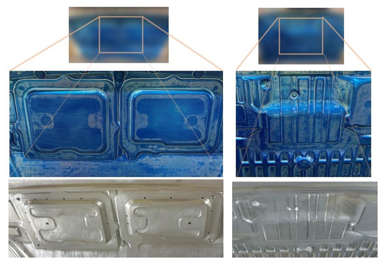
Figure 9 Die Spotting Results
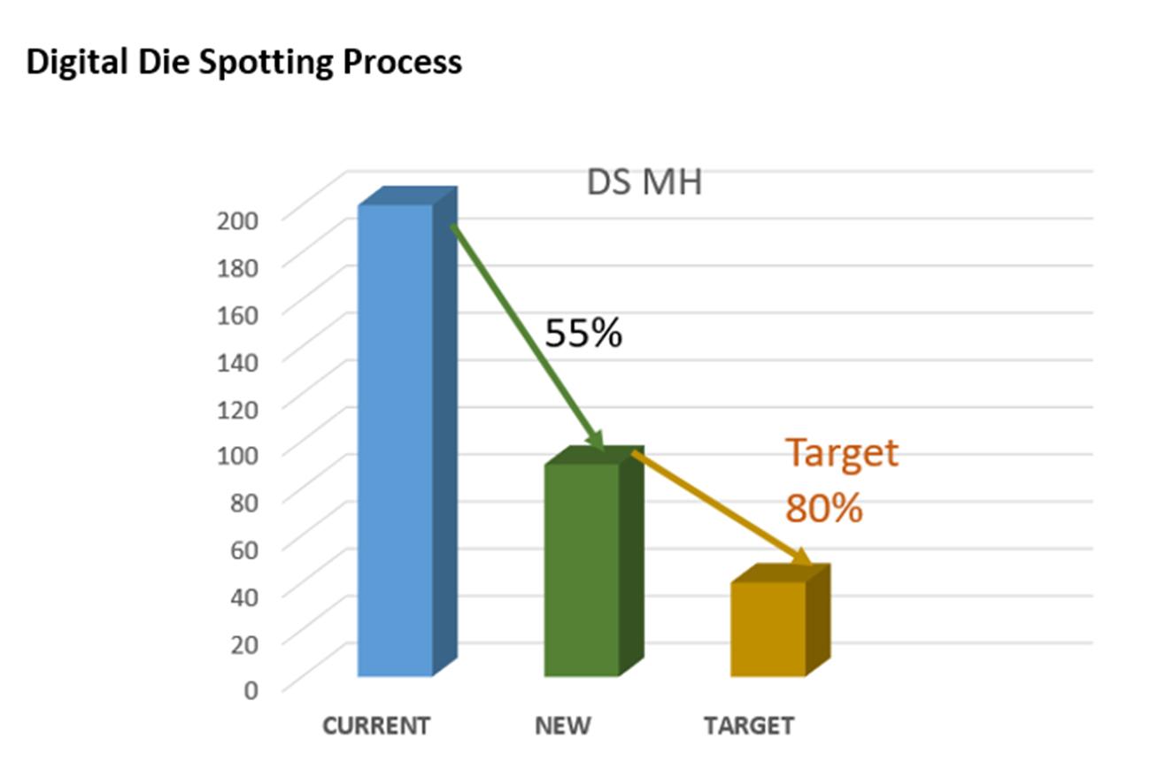
Figure 10 Digital Die Spotting Process Man Hour
Fig. 11 Yean Tool Shop
Summary
The existing Digital Die Spotting Process in Fig.1 was based on checking the results from AutoForm and applying Die Spotting compensation by engineering with little field experience, which was time consuming since the modeling was done manually.
And since the sidewall area’s Die Spotting needed to be done at an angle, there was a problem of Die Spotting on the sidewall due to the same amount.
Based on these contents, the new function of AutoForm R10 “Die Spotting” was actually applied to solve the problem of Die Spotting’s modeling time and Die Spotting on the side wall. In addition, since the existing Digital Die Spotting Process was applied, the on-site die spotting time was similar to the previous work, but the engineer’s man hour was reduced by more than 90% compared to the previous one. Consequently, we consider this project as success case of using AutoForm R10 ‘Die Spotting’. In the near future, AutoForm R10 ‘Die Spotting’ will be applied to other parts.
Thank you to our partners at YE-AN Korea.


?")


