
Addressing the Question of Simulation Accuracy from Another Angle
In this post AutoForm Technical Director Bart Carleer revisits the question of AutoForm’s accuracy and challenges readers to not merely go by judging what is before their eyes in tryout, but to reexamine input parameters. He also demonstrates how small changes of input can result in massive consequences in forming simulation results. Even more interesting: he questions if benchmark studies demonstrate accuracy well or whether they are influenced by unaddressed factors?
One of the things that I am often asked is “How accurate are you?” They often ask for a ballpark figure: “80%, 90%? Give us an idea.” For me this is an impossible question to answer and I’ll explain why. But also, I’d like to illustrate the issue of sensitivity.
Throughout my career I have rarely come across any unified agreement for a definition of what accuracy is. Everyone seems to have their own take on it. Therefore, first, we need to define that and why our definition is valuable. At the risk of sounding like a “Mr. I told you so,” some flaws in contrary ideas should be pointed out in developing this understanding.
Here is our definition of accuracy:
“Accuracy is viewed by comparing a simulation with the experimental result.”
End of story? Not quite. It really means first we simulate the forming of the part in our software and then we compare it with the real part produced in tryout. One of the assumptions some people make is that you can compare one particular software with another. They’ll try comparing AutoForm results with results from another brand like LS-Dyna or Pam-Stamp. Is this really of any value? Not at all! If talking about accuracy we have to only compare software, whatever its brand, with how well it matches reality.
But What About Benchmark Studies?
Everyone loves benchmark studies. They generally compare various simulation tools and reality, normally for a specific part or shape for the experiment. The parts or experiment under investigation are well defined and in these publications you see a side by side comparison or table of how well or badly the various software products performed. Naturally these attract readers.
But, do they accurately represent reality?
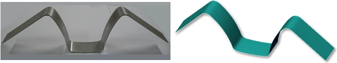
Fig. 1: Numisheet 2011 U-Bend Benchmark.
Yes, benchmarks represent reality – however only a limited scope of reality. Industrial stamping processes are much more complex. Now you’re looking at the impact of accuracy over a range of operations, all for one part. Still, at the very basis of all such complexity one thing really determines accuracy. Regardless of your own definition, we must have similarity between the simulation set up and the reality set-up, and look at how they match. That means, as long as the input of the simulation and the input of the experiment are identical (as far as can be achieved) then the output of your simulation is going to be – or should be – quite identical with the real part and therefore accurate. But, now, you have to open Pandora’s box.
There are a lot of factors that go into the input. All these combine for the whole of accuracy.
To name just a few: material properties, mechanical properties, tribology systems, failure criteria, also geometries, tool kinematics and process parameters such as forces etc.
When you compare an academic example, such as the “U-bend” above, with the engineering of a door, then you see that the academic case you are dealing with has far less complicated variables than in an industrial production environment. The door has a drawing operation, segmented trimming, some flanging etc. The boundary conditions are therefore far more complex for its engineering.
For the “U-Bend” study, I am not saying that it is “less accurate,” but rather – it is far easier to ensure that your input for simulation matches the input you have for the experiment. Such benchmark studies are nice for comparing brands and their solutions at that level, but having greater in-house expertise is also a factor in the real world and having that additional support ensures greater accuracy for the more complex productive environment. Now you have to look deeper at those brands.
Of course, if you can’t match your simulation to reality for such a basic part, you’re in very big trouble. What then will happen with more complex parts? In either case, from one side of the difficulty spectrum to the other, the name of the game is matching input to tryout. Quality in, quality out.
Closing the Gap Between Engineering and Reality
Now, input parameters would be straightforward if we knew everything from the start. In reality lots of engineering tasks are being carried out simultaneously. When simulation-engineering starts so does method planning, die design and the making of the tool pattern can overlap with some of the engineering tasks. Casting and surface design might overlap with some of those as well. All of these accumulate changes that need to be considered as input parameters within your simulation set up. Otherwise it won’t match reality any longer. Without trying to sound like a broken record, “You need to ensure that your real-world engineering adjustments are well-communicated and constantly updated!” This is a constant message from AutoForm and we have solutions that help with this.
There are other problems though. In reality digital engineering and tryout cannot be performed in direct sequence – they are separated by a time lag. This is the danger zone. Things happen in pattern design, casting, surface design and tool manufacturing. Sometimes it takes several months for all this to be done between the last simulation and the first stroke to turn out any part. The challenge is to ensure that digital engineering still matches your “experiment” (i.e. tryout) at the end.
Needless to say, if you’ve started out with a green simulation then it should work, so long as everyone worked accordingly and perfectly matched the last green simulation! However, when it comes to the final part and it suffers from thinning and splits does that mean the software was not accurate? Or does it mean something else? We want to compare apples to apples. You therefore have to secure an identical set up. But, what was first, the chicken or the egg? Are we simulating what we have on the floor or does simulation determine what must be used? Where simulation is applied to define the process setup during engineering it would be nice if we can entirely match reality to that green simulation. We know that certainly it would work. The software does not lie.
But, in reality a tryout team sees what they have before their own eyes, looking at what they’ve got in tryout. Now they’ll scream “Hey, your software is not accurate!” But, as usual some references have been switched over time. They can’t see this, or don’t consider it, and it’s all too easy to blame the software. The issue lies in comparing those apples to oranges.
Therefore, in order to effectively apply simulation in an industrial environment we firstly need accuracy of input. Secondly we need process robustness and a generous process window. Thirdly we need reliability and numerical stability. This is the magic recipe.
Input Parameters are Sensitive Guys
It is astounding just how sensitive the results can be to simple mechanical criteria. Change a few things, even just a little bit, be it material properties or process parameters, and it can result in drastic consequences in production.
Let’s illustrate this using two real-life examples:
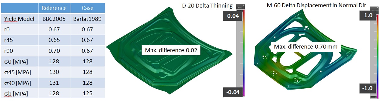
Fig. 2: Mechanical results sensitivity to input variables.
The input parameters for simulating mechanical properties include the hardening curve, yield model, thickness and rolling direction. Side by side you see the reference and the input differences for case study of the same part. The input changes result in a springback difference of 0.7 mm, which for any OEM is out of tolerance. Yet the input changes were very small.
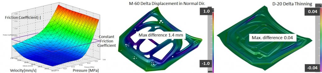
Fig. 3: Tribology results sensitive to friction models.
Tribology is also a sensitive issue. Its defining factors include the tool surface, lubricant and the sheet surface with its own roughness. When using an advanced friction coefficient model vs. a constant friction coefficient the results can be extremely different. In the case above you see up to 4% differences in thinning and for springback a difference of 1,4 mm. This is really significant and again the input changes were minor.
There are many more examples we have illustrated in recent presentations. But you get the idea.
In the end, accuracy is not about comparing different forming simulation brands on benchmark tables. AutoForm does extremely well on those, but we always advise that there is much more to the story. Accuracy can be achieved at a very high level. Ultimately, it’s all about making sure you have identical boundary conditions, no matter which phase you look at. If you make any physical changes, then make sure you recommunicate and re-simulate to ensure you’re in the green. If you’d like to have support in capturing any of those adjustments being made by later departments and engineers, especially long after your first simulations, then you may be interested in taking a closer look at our tryout solution here.
Bart Carleer, AutoForm.
New readers, don’t forget to sign up to our blog. We only send a once per month email update on important post you might enjoy. Stay informed on the latest sheet metal forming post by signing up now.


?")


")