In automotive manufacturing, the CMT (Cold Metal Transfer) welding process is widely used to join thin sheets due to its low heat input, minimal spatter, and high welding quality. However, surface defects can still occur after CMT welding in production, significantly affecting surface quality and subsequent coating performance.
Using a side panel as the case study, this article applies AutoForm Assembly analysis to identify the causes of these surface defects and determine effective countermeasures.
Issue Description
After CMT welding, a noticeable surface defect appeared on the side panel, as shown in Figure 1. Previously, there was no effective way to predict this issue, let alone analyze its causes. The defect typically had to be physically reproduced on-site, followed by trial-and-error analysis and corrective actions. This process often led to unnecessary time and cost overruns.
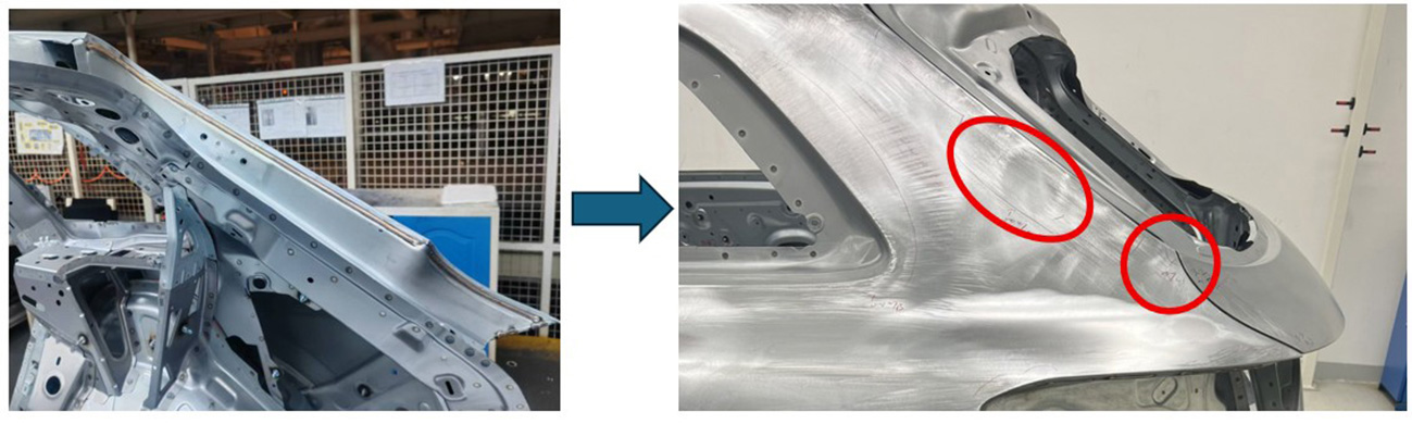
Figure 1: Surface defects after CMT welding
Trouble shooting
After confirming that the individual part quality and fixture status were acceptable, two possible causes remained: dimensional fit-up between the individual parts and thermal deformation caused by CMT welding.
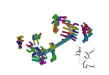
In AutoForm Assembly, actual welding process parameters can be input, and the CMT heat source power and travel speed can be defined. This allows on-site issues to be reproduced while also accounting for the status of the individual parts, as shown in Figure 2. In this case, the CMT welding lines were defined according to their actual positions and lengths. Eight CMT welding lines were defined, with the longest measuring 566 mm and the shortest only 22 mm.
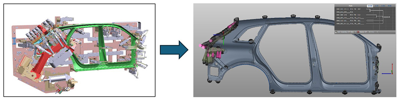
Figure 2: Simulation set up based on actual fixture
The study was divided into four steps to analyze the results under different input conditions and identify the root cause of the surface defect:
- Theoretical State
- Part Dimensional Deviation Only
- CMT Welding Only
- CMT Welding + Part Dimensional Deviation
Results
The results helped clarify what was causing the surface defect. The four cases are discussed below.
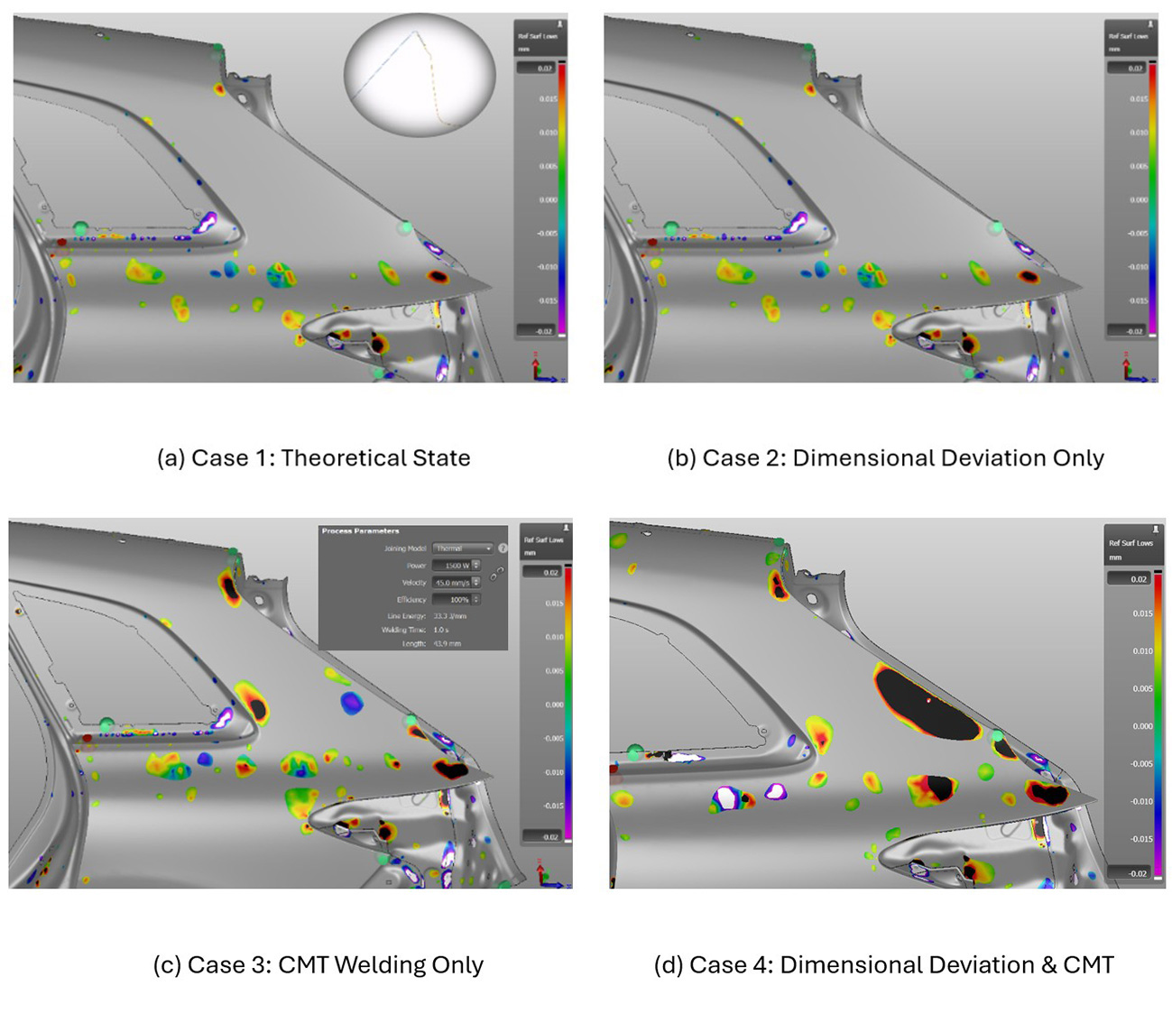
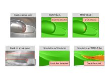
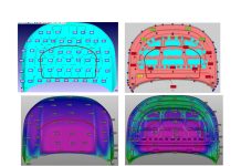
Figure 3: Surface defects under different input conditions
Case 1
Under theoretical input data, with no deviations in the part or fixture and no thermal effects, no welding deformation or surface defects occurred after welding.
Case 2
Based on the measurement report, actual part deviations were incorporated into the analysis. Without thermal effects, no welding deformation or surface defects occurred after welding. In practice, when the parts were joined with glue instead of CMT welding, no defects appeared either.
Case 3
When only the thermal effect was considered, using the actual CMT welding power and velocity, the part showed slight changes after welding, indicating a tendency toward deterioration. However, the effect was still much milder than the actual results. In this scenario, the product was still based on theoretical input data.
Case 4
When both actual part dimensional deviation and CMT welding were considered, the simulation results showed a clear surface defect after CMT welding, as shown in Figure 3. Further verification showed that adjusting the CMT parameters did not significantly change the severity of the surface defect, while changing the part fit-up state had a notable effect.
Summary of Virtual Simulation
Based on the comparative analysis of the above scenarios, the following conclusions were drawn:
- The surface defect was caused by the combined effect of CMT welding and part dimensional fit-up.
- Although CMT welding alone did not show a strong correlation with the surface defect, the defect became more pronounced when part fit-up was poor.
Virtual Tryout
Based on previous project experience, optimizing the flange angle to improve part fit-up, or matching, is an effective way to resolve this type of surface issue. In practice, changing the drain channel would have been easier and less costly from a tooling modification perspective. However, the AutoForm Assembly virtual analysis results showed that modifying the drain channel had little effect on the surface defect, while modifying the side panel significantly reduced it, as shown in Figure 4.
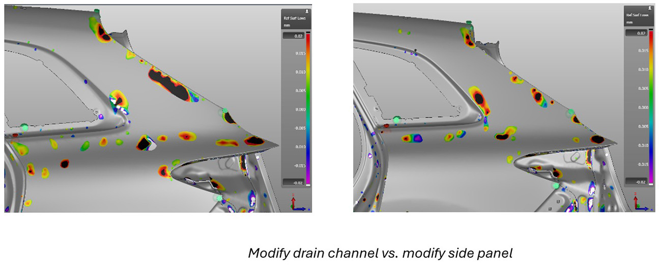
Figure 4: Virtual tryout results
The final tryout results showed that after the side panel flange angle was optimized, the surface defect was clearly eliminated. No further surface defects occurred in subsequent production.
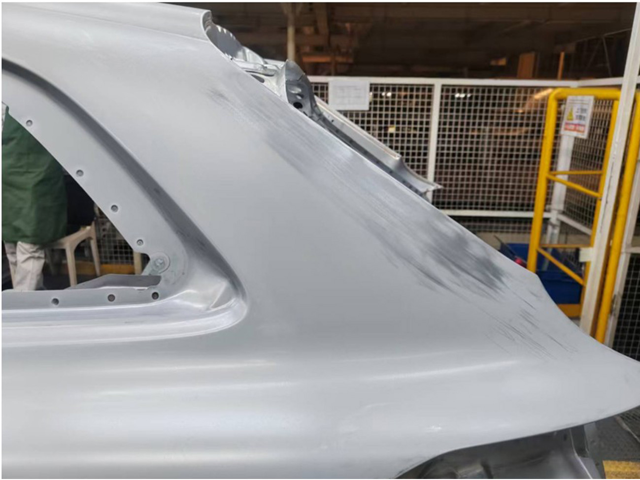
Figure 5: Validation of CMT effect after optimization
Conclusion
Through multi-scenario simulation analysis, this study determined that the main cause of surface waviness after CMT welding was part dimensional deviation, rather than CMT welding deformation itself. By optimizing the side panel flange angle, the simulation confirmed the effectiveness of this countermeasure and provided a useful reference for future process optimization.
Zhang Peiran noted, “AutoForm Assembly-based laser welding simulation enables rapid identification of the main causes of surface defects after CMT welding, supports virtual tryout of the issue, and helps determine on-site corrective actions. This reduces the number of physical trial-and-error cycles, as well as debugging time and cost.”
About the author:
Author: Zhang Peiran
Dept. of author: FAW Volkswagen, T-G-VSC, Product Technology and Ramp Up
Special thanks to Sam Wu, AutoForm China.