ABSTRACT
During development in the automotive industry, significant efforts—both virtual and practical—are specifically directed toward the manufacturing of stamped parts and welding processes. To ensure compliance with specifications and achieve high-quality dimensional assemblies, it is essential to consider various factors involving raw materials, processes, and products.
As a practical example, consider the Front End Tie Bar of a vehicle, an assembly composed of 24 stamped parts. Although the individual stamped parts were dimensionally approved and the welding devices were in nominal condition, the physical assembly did not fully meet dimensional requirements. Given the complexity of welding process variables and the resources (time and cost) required for physical interventions, a decision was made to carry out a virtual analysis (using AutoForm Assembly) to support process-improvement decision-making.
Through these simulations, a pilot project was executed to integrate the entire process chain, establishing an efficient connection among process engineering, production, and quality teams.
INTRODUCTION
This study addresses the importance of digital transformation in engineering, highlighting its influence on process optimization and on improving efficiency in various applications. This evolving phenomenon is driven by the growing adoption of virtual resources, which are redefining how engineers design, construct, and manage projects. The benefits include greater efficiency, accuracy, and collaboration among teams, with process virtualization being a key aspect discussed in this study.
Dimensional accuracy in welded parts and assemblies is especially critical, making the virtualization of welding processes a central strategy for achieving such accuracy. In addition, advantages relating to efficiency, productivity, and integration of the entire process chain are examined, with practical examples focused on the Front End Tie Bar assembly (Figure 1). These examples illustrate improvements in quality and specification compliance.
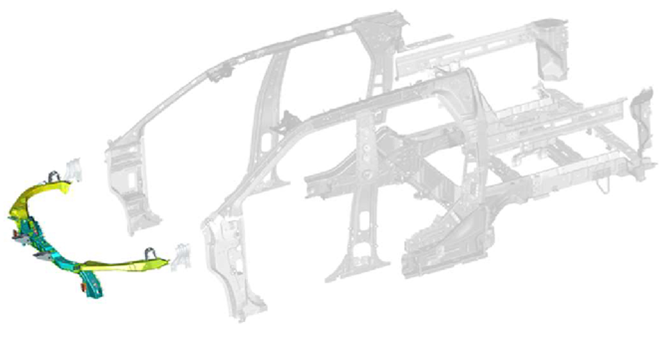
Figure 1. Front End Tie Bar.
The literature contains numerous studies on the digital transformation of dimensional accuracy in the automotive industry, often centered on the effect of stamping parameters on individual components—such as uplift loads, friction coefficients, raw material properties, and stamping tool radii [1,2]. Gösling’s dissertation [3] explores multiple springback compensation strategies and stamping parameter combinations in springback control, highlighting the complexity of these processes and the specialized knowledge they require.
The virtualization of individual component processes has been well established in the automotive industry for many years, recently expanding to assembly processes [4]. Existing research on the simulation of joining processes is regularly oriented toward aspects such as temperature distribution, metallography, and residual stresses [5–6]. Although this field is expanding, few studies specifically address large-scale assembly. An example can be found in Tinti et al. [4], who developed an assembly simulation of a hood in four joining stations. Another instance applied computational solutions to the outer trunk lid assembly of a different vehicle [7].
Generally, literature on the impact of heat application and mechanical forces on the joining of large assemblies of stamped components remains scarce. These factors are often overlooked during the joining process development phase [8]. Empirical evidence indicates that joining dimensionally stable parts does not necessarily result in dimensionally stable assemblies, a viewpoint shared by Schuler, Liewald, and Bezerra [8]. They also propose optimizing the process flow chart, as shown in Figure 2, by reducing the number of loops needed to correct stamping tools and welding devices, thus avoiding ineffective efforts that do not enhance final-assembly dimensional conformity.
Resistance welding is one common method for joining metallic materials. Heat is generated as electric current passes through the parts to be joined—due to the electrical potential difference between the electrodes and welding gun arms—forming a molten puddle that fuses the parts after cooling. This process, especially in the form of spot welding, is widely applied in automotive assembly [9], with its usage equaling that of all other joining processes combined in luxury vehicles [6]. It is also employed in aerospace and construction for its speed and efficiency.
This study focuses on the Front End Tie Bar assembly, which did not fully meet dimensional requirements even though many of its individual parts were within specification. Raw material variations, process factors, and product complexities are examined, as well as the application of virtual analysis as a tool for improving processes and resolving dimensional deviations. The pilot project—geared toward optimizing integration of the process chain—represents a strategy to enhance product quality and compliance.
Information flow within large corporations is invaluable for optimizing operating costs. In manufacturing, it is now common to have systems that connect production to various departments, sending real-time production line data to monitor batch manufacturing and speed up decision-making in case of issues (Figure 2).
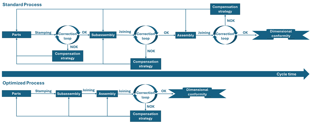
Figure 2. Flow chart optimization proposal; adapted from [8].
Despite these advancements, the development phase rarely sees similar cross-departmental connections, which could help synchronize efforts and optimize production costs. The automotive industry has a long history of pushing technological boundaries—for instance, Henry Ford’s [10] groundbreaking approach to mass production achieved major productivity gains by assigning repetitive functions to workers. Today, the drive to improve processes continues, with teams focusing on advanced production models such as Industry 4.0, aiming to create a dynamic system that integrates departments and production facilities, improves information flow, eliminates waste, and continually reduces the carbon footprint.
To remain competitive, companies must be adaptable to the latest trends, extracting maximum capability from their plants with high quality and lower cost. Implementing such changes requires not only overcoming existing paradigms but also time to review and adjust methods and processes. Digital tools offer valuable opportunities to predict failures, support more confident decision-making, and eliminate trial-and-error approaches. Figure 3 contrasts the pursuit of dimensional excellence with the challenges of reducing lead times and costs.
Breaking paradigms is often one of the most complex steps in any transformation. The Fordist model resulted in departmental and individual roles where each party focuses solely on its own objectives. This dynamic creates siloed environments and can introduce various risks and inefficiencies.
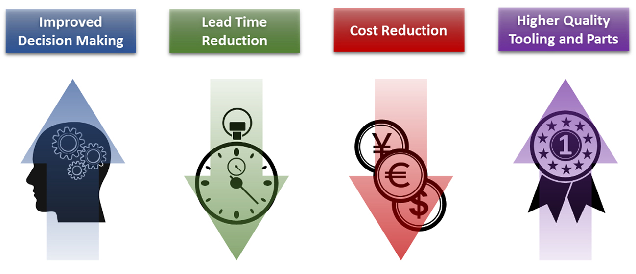
Figure 3. Quality optimization against lead and cost reduction.
Consider the final assembly of a vehicle. Countless steps, departments, and suppliers are involved, with multiple interconnected tasks. In the car body framing process, for instance, the metal parts come from the Press Shop, which receives stamping tools from the Tool Shop. If each department works in isolation—if the Tool Shop aims exclusively to provide the best stamping tool possible, and the Press Shop focuses only on producing the best stamped part—excessive effort may be expended without necessarily ensuring the best assembly mounted by the frame. Figure 4 illustrates the proposed process for developing metal parts, showcasing how current software resources can virtualize and integrate much of the cycle, from raw material planning to joining processes.
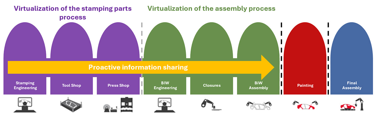
Figure 4. Proposed process for the development cycle of metal parts.
Would it truly be most effective if each department solely aims to achieve its own objectives? Were the processes assertive and cost-effective, using only what was necessary to ensure the best product quality throughout the entire chain? Was the stamping tool delivered to the Press Shop built with the vehicle production life cycle in mind? After all, the majority of costs during a product’s life lie in serial production, not just in approval events. Even if the stamped parts are within tolerance and delivered to the BiW assembly, is that enough to ensure that all components and sub-components are assembled without rework or adjustments?
These are questions that can be answered in advance, by means of digital resources, even before any production facility is built. Hence the importance of preparing the digital twin of the process, a key element of Industry 4.0 to be carried out by the engineering departments, as shown in Figure 5. This approach allows impacts to be anticipated and ensures greater assertiveness in deliveries between each department, aiming for the best product at the lowest cost.
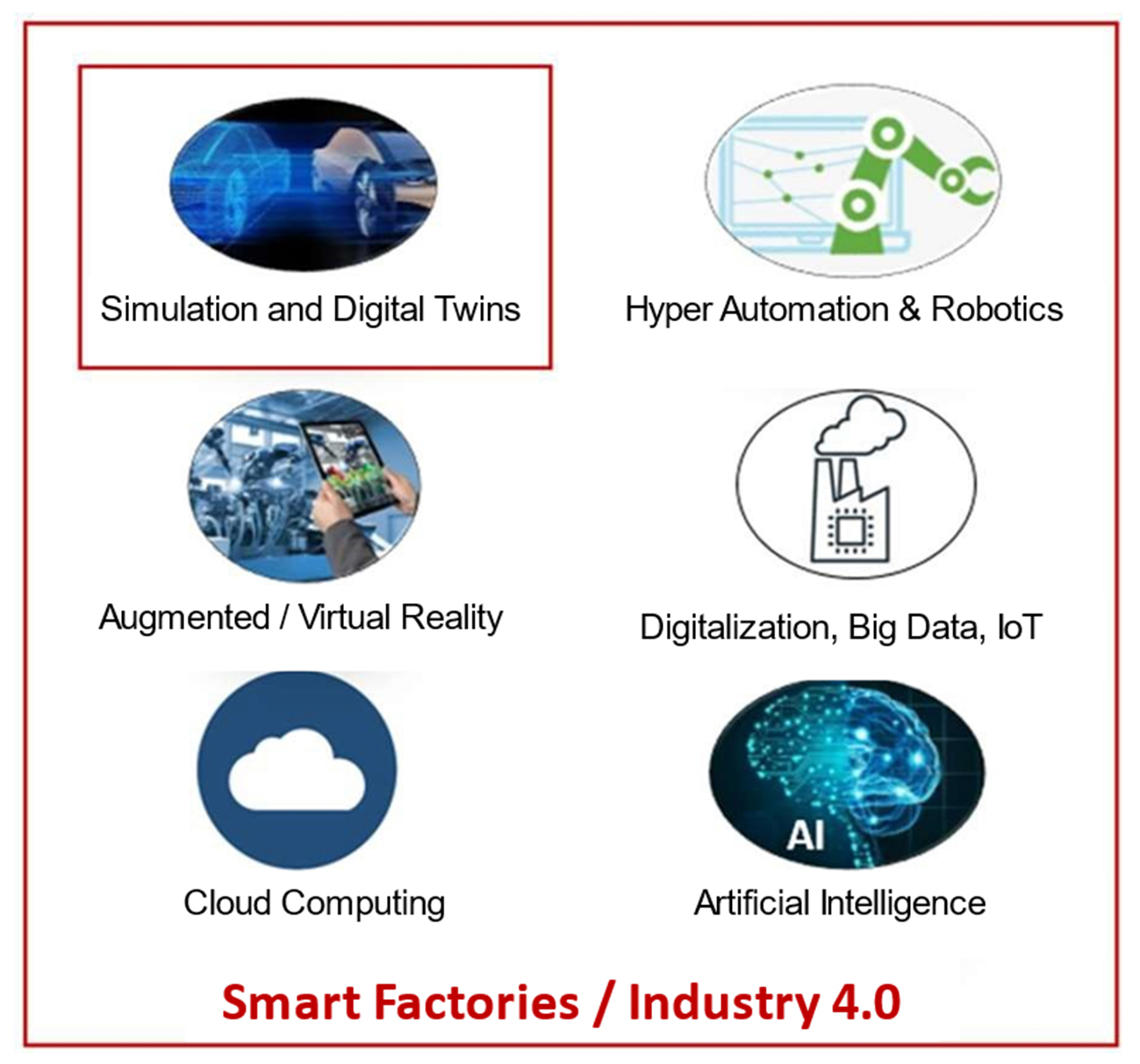
Figure 5. Digital twin of the process in the context of Industry 4.0.
Here, it’s worth highlighting the importance of virtual analysis in assessing dimensional accuracy, using the Front End Tie Bar assembly as a case study. Decisions supported by virtual analysis are discussed in terms of their positive impact on the entire cycle of engineering, production, quality, and technical support. The inclusion of representative images illustrates the evolution of the process and highlights the benefits of a digital approach when seeking dimensional excellence in the automotive industry.
METHODOLOGY
In the proposed methodology, discussions among the various departments can begin in the engineering phase, starting with the definition of the product, involving product engineering and manufacturing. Both teams work together to make the product feasible and less complex, reducing the purchase cost of stamping tools, hemming, and welding devices. This also minimizes rework costs if, at a later stage of the process, a manufacturing problem is identified that requires modifications that may affect already completed stages.
With this phase completed, manufacturing engineering connects with development engineering, which in turn receives the product feasibility data. A study then began to define processes with a focus on assembly and series production, aiming to optimize operations and ensure production repeatability. This can be done by creating production maps that will assist the stamping and hemming teams. Note that there is a constant exchange of information between the stamping and BiW engineering departments, since obtaining assemblies within required dimensions (and not just each individual part) is critical to ensuring the proper assembly of the complete vehicle.
The involvement of employees from the manufacturing areas is essential throughout the development process because they possess extensive knowledge and can provide valuable information for decision-making. In addition, they can gain early insight into the process, since they have participated in the engineering phase and understand the role of the process’s digital twin. As a result, they can direct and build exactly as planned, minimizing divergences between simulation results and the physical world. Even if deviations occur, there will be a communication channel and openness to direct feedback between the shop floor and engineering—a crucial factor in improving the methodology and identifying potential issues.
Considering that multiple potential failures can be identified and addressed during the development process, the Tool Shop will be able to deliver parts for approval events with higher quality and shorter try-out times, ensuring the integrity of the stamping tools as designed. In the Press Shop, after the home line try-out, process stability and repeatability will be guaranteed, since the processes were developed using simulations that account for different situations that might arise during production—for instance, variations in material properties due to changes in manufacturing lots. Figure 6 shows the application of the process digital twin in this work, a key element of Industry 4.0, where striving for excellence involves integrating virtual analysis departments with production facilities.
The digital twin concept also extends to the Body Shop. As in the Press Shop—where the forming processes for individual parts are simulated under varied conditions to ensure that the first samples meet high quality standards with fewer adjustments—the same principle applies in the Body Shop.
Process details can also be simulated to ensure overall assembly quality, including the simulation results of individual parts. Thus, the Press Shop’s objective becomes delivering parts that meet the assembly’s dimensional requirements. In the engineering phase, it can be determined whether dimensional deviations of each part will affect the assembly or whether certain parts should be intentionally deformed outside nominal conditions. This prevents unnecessary time, rework, cost, and effort spent on adjusting either the stamping tool or the welding device. To implement process digital transformation, various software solutions are available—such as the one used in this study for metal parts and assembly. The framing software approach is divided into four stages, referred to as Use Cases (UC).
In Use Case 1, a process and product feasibility study is conducted, analyzing the initial conditions for joining the parts. Only CAD-0 is used—i.e., nominal product geometries—making it possible to verify potential impacts on assembly quality caused by the process or by part features. In Use Case 2, the process is mapped, and changes are implemented to meet quality criteria. At this stage, it is necessary to use the results of simulated stamped parts to bring the digital twin even closer to the actual process [11]. Here, the main focus is on the assembly’s dimensional requirements and surface quality.
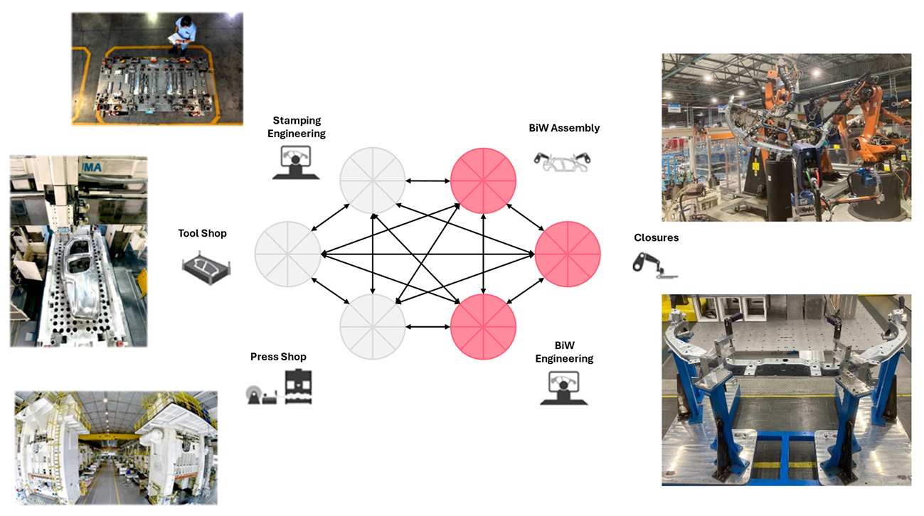
Figure 6. Application of the digital twin of the process, a branch of Industry 4.0.
Use Cases 3 and 4 focus on the manufacturing areas and their connection with engineering. In other words, if a problem occurs on the shop floor, the line devices and individual parts are digitized so the digital model can be aligned with the actual process. Once the process has been characterized with the parts received from the try-out in Use Case 3, virtual adjustments are carried out in Use Case 4 to solve the problem, thereby minimizing production waste. These adjustments may involve optimizing clamp positions, welding sequences, pilot positions, or even modifying the geometry of individual parts.
During the initial phases of the project, when the stamping tools and welding devices were being constructed, the springback of the components was estimated through finite element simulations. This approach enabled springback compensation in the stamping tools, ensuring the geometric conformity of the individual parts. The nominal stamping tools were adjusted according to the calculated springback. However, the effect of the joining process on dimensional deviations—which could justify allocating resources to this area—had not yet been fully explored before this research. The aim here is to investigate the digitalization of the joining process for a vehicle’s Front End Tie Bar assembly using simulation software. Because these products are notably complex, springback plays a key role in meeting the assembly’s strict dimensional requirements.
The pilot project implemented is a three-stage plan integrating the entire car body assembly process chain. Before the pilot project was established, parts were stamped and joined following the usual workflow applied in the automotive industry, meaning there was no opportunity to use computational resources to support assembly development, even though such resources were employed for the individual stamped parts. The first step involved evaluating the Front End Tie Bar assembly’s dimensional accuracy by simulating its process with CAD-0 surfaces and welding devices—namely, nominal surfaces and clamp positions (Use Case 1). The objective of this initial approach was to determine the impact of the welding process in scenarios where the stamping processes perfectly matched the nominal product geometries.
Next, the CAD-0 surfaces were replaced with stamping simulation results, marking Use Case 2. This procedure incorporates crucial information—such as thickness variation and springback calculations—generated by the simulations. However, one of the main challenges in stamping can still significantly affect car body assembly: establishing robust manufacturing processes that ensure geometric conformity, despite variations in raw material mechanical properties and typical process noise related to friction, stamping tool maintenance, and more.
The third and final step was carried out after scanning the individual formed parts that exhibited the greatest dimensional deviations. By scanning the real product’s mesh, the actual geometry replaced what was derived from the stamping simulation. In this particular project, where simulation was not applied during the development of the assembly devices, this approach can yield the most accurate digital twin of the process. Nevertheless, each digitized product was assigned thinning information based on the finite element models generated in the second step. At this stage, a hybrid Use Case was implemented, involving Use Cases 2, 3, and 4, as part of an effort to virtualize what was already happening in practice—even though some corrective actions had already been taken based on the expertise of the involved teams. Some parts, which did not exhibit any noteworthy dimensional deviations, were not replaced with scanned data. The final results from this third stage were compared to the actual measurements of the Front End Tie Bar.
DISCUSSING THE RESULTS
In the practical example described, the Front End Tie Bar assembly of a vehicle was found to be dimensionally out of specification, despite most individual parts and welding devices meeting standard tolerances. The virtual analysis in the software made it possible to evaluate the complexities involved in the welding processes. This digital strategy provided a basis for decisions that improved the process and the broader cycle of engineering, production, quality, and technical support.
RESULTS OBTAINED BY AETHRA AND GENERAL MOTORS
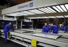
It was established that a digital twin of the welding process enables a virtual analysis of the entire assembly sequence designed by the engineering department to identify the dimensional impacts of these choices. Thus, in the project at hand, by using Use Case 1 (the first stage), it was possible to verify and correct the assembly sequences previously developed in the engineering phase, now validated through simulation. Figure 7 shows an example of an intermediate station in the assembly process.
The welding spot sequence is another input that can directly affect the dimensional stability of the assembly. This effect can be included in a digital twin simulation of the process by considering the thermal contribution of each weld spot and the size of the weld nugget. In the literature, it is common to cite the interface between two sheets as the critical point of resistance for the formation and growth of the weld nugget in Resistance Spot Welding (RSW) [12–14]. Furthermore, other processes such as riveting and clinching (using either a fixed or mobile die) can also be evaluated. Figure 8 illustrates these processes from top to bottom, respectively.
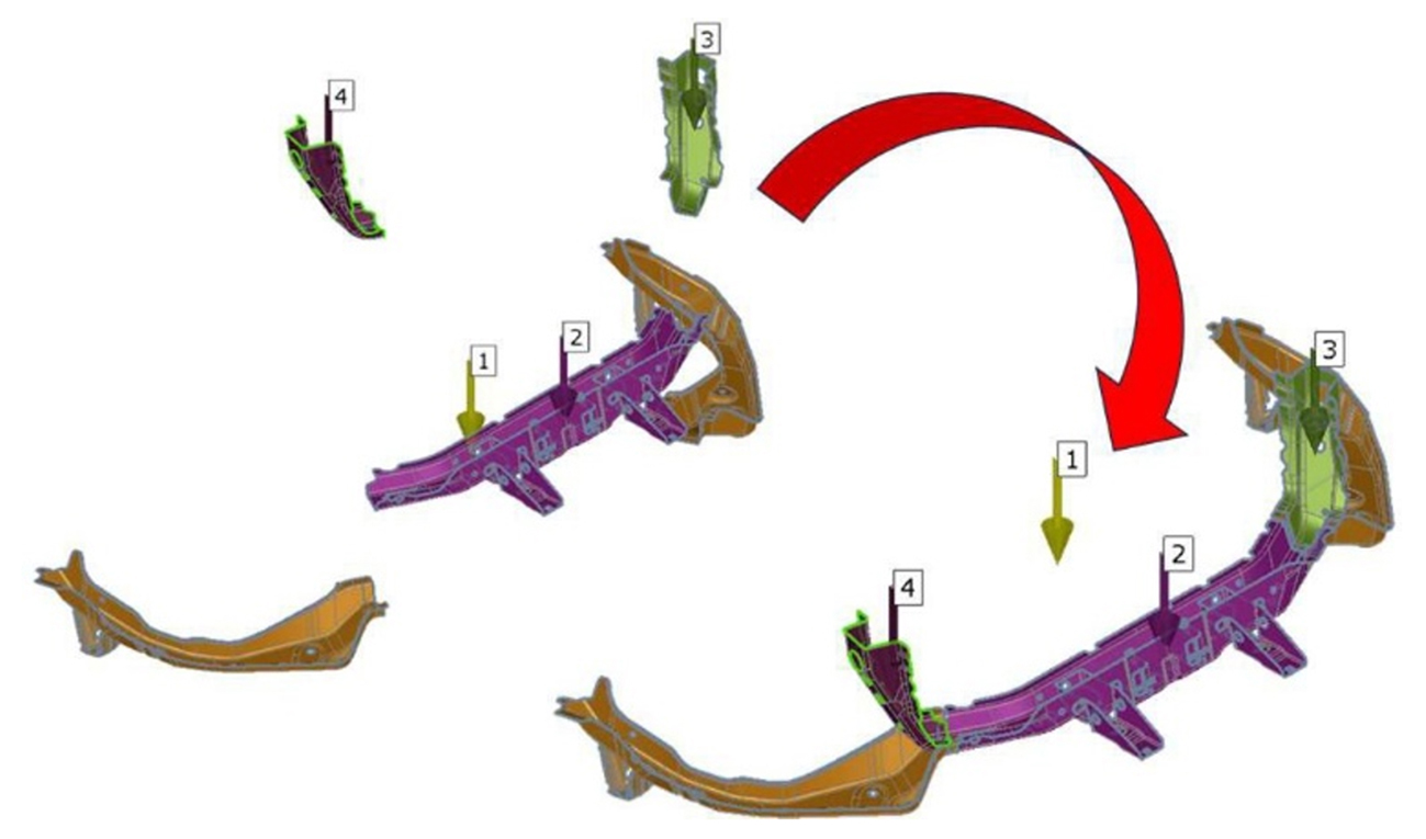
Figure 7. Intermediate station example of the Front End Tie Bar assembly process.
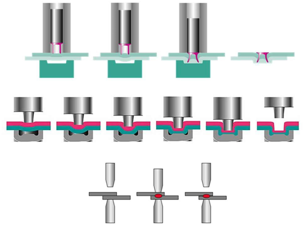
Figure 8. Joining by riveting, clinching, and RSW, respectively.
In an assembly simulation, the stress exerted by welding spots, any thermal contribution they generate, and the welding spot sequence can directly influence the dimensional outcome of the BiW assembly. Typically, the sequence of welds is chosen solely based on cycle time and welding access. However, process simulations now enable evaluating how this sequence affects the assembly’s dimensional accuracy. Figure 9 shows two different welding paths applied to an assembly station. If problems arise, the spot-weld sequence can be changed, and the new dimensional results analyzed.
Other validations involve checking how the parts are clamped within the welding devices, taking into account gravity and the weight of each part. The order in which the parts are placed is also considered to identify possible instabilities that could lead to dimensional deviations in all six degrees of freedom (rotation and translation). These checks are performed virtually, as illustrated in Figure 10. Depending on the stage in question, welding devices can also be optimized by removing any extra towers that serve no real clamping function.
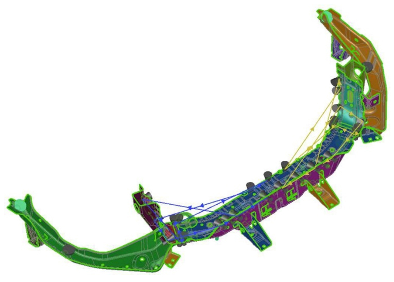
Figure 9. Different welding sequencing paths applied to assembly simulation.
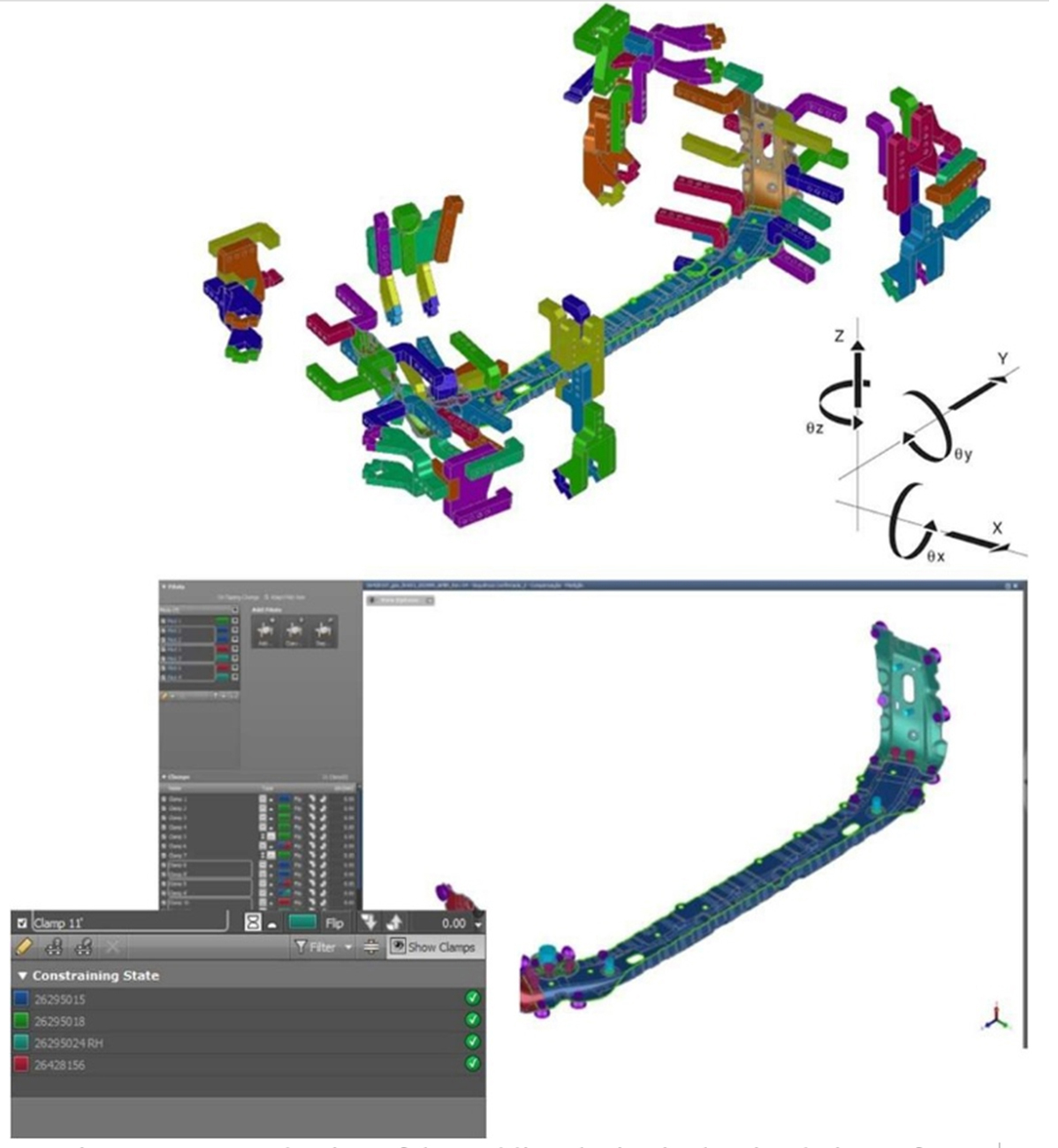
Figure 10. Reproduction of the welding device in the simulation software.
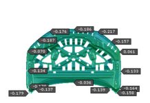
Building on these considerations, a preliminary assembly study was conducted that incorporated key process variables. Although the Tie Bar set was already in production, a reverse-engineering approach yielded an initial assembly analysis that identified areas with deviations similar to those seen on the shop floor (highlighted in Figure 11).
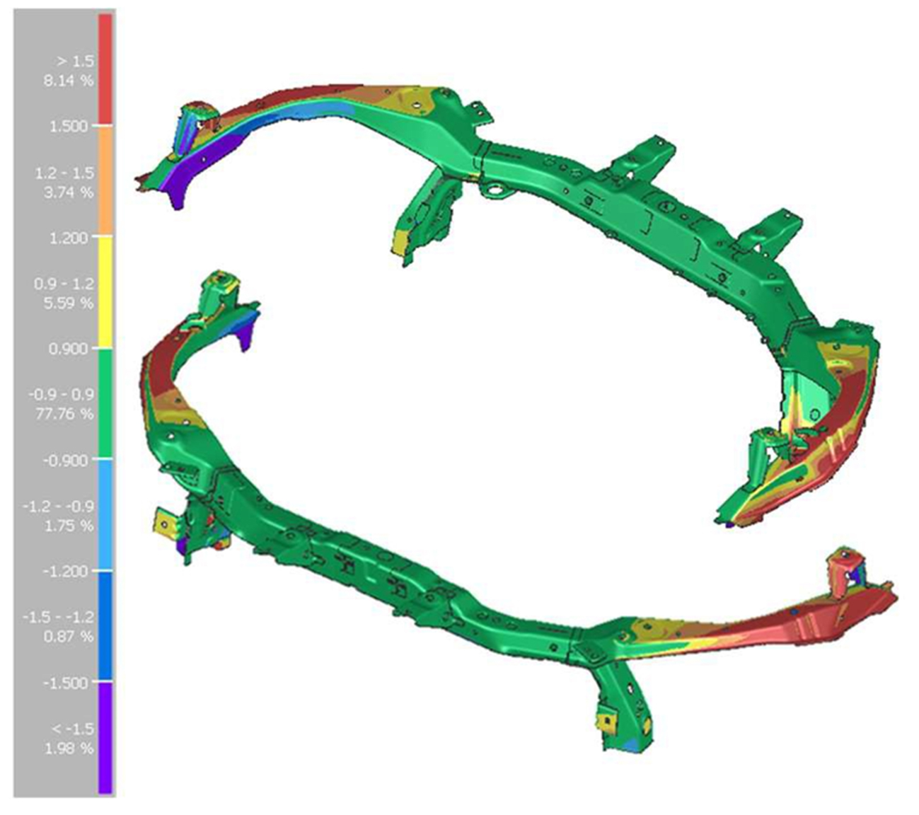
Figure 11. Dimensional deviations found for Use Case 1, expressed in millimeters.
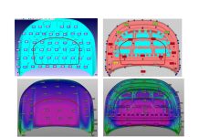
As outlined in the methodology, the next step introduced additional information (Use Case 2). Consequently, the simulation showed greater dimensional deviations because stress, thinning, and springback data—along with the deviations of individual products—were now factored in. This led to worsened dimensional issues in previously affected areas and also revealed new, smaller deviations. The portion of the assembly meeting the geometric shape requirement (green regions) decreased from 77.76% in Use Case 1 to 63.53% in Use Case 2. Figure 12 illustrates these second-step results.
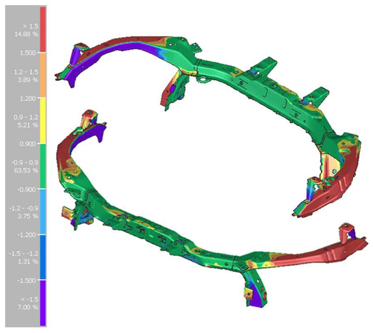
Figure 12. Dimensional deviations for Use Case 2, in millimeters.
Following the simulation of Use Case 2, there was a considerable increase in dimensional deviations across the assembly and an aggravation of mating areas. This is due to the additional errors or deviations layered onto the process, compared to the initial study in Use Case 1.
Up to this point, no specific efforts had been made to improve the process. Therefore, instead of showing enhancements, the simulations revealed increasing deviations in the assemblies.
Finally, a hybrid simulation encompassing Use Cases 2, 3, and 4 was performed. The digital scans (capturing springback deviations) of the most significantly distorted parts, along with the simulation results of the remaining parts, supplied the model with real-world stress, thinning, and springback data that align with current production. Because this is a reverse-engineering approach, the support points had to match the actual welding devices, which themselves had undergone corrective actions through multiple practical try-out loops. Figure 13 displays the measured dimensions, demonstrating that most shape areas are now compliant—an outcome reflecting extensive teamwork in the practical process. At the same time, these results underscore the urgent need to virtualize assembly work, reducing the effort and cost associated with repeated trial-and-error setups on the shop floor.
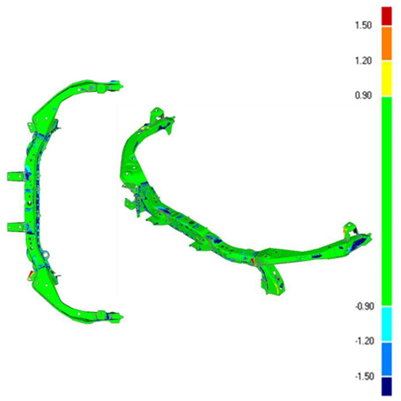
Figure 13. Actual dimensional deviations of the Front End Tie Bar
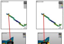
The simulation results are illustrated in Figure 14, and the real-versus-virtual correlation is presented in Figure 15. In most of the geometry, the deviation is under 0.3 mm, although some localized regions show deviations over 0.6 mm. At this stage, the objective is to recreate in the virtual environment what already occurred in practice, which contrasts with the usual process flow, where engineering data guide production. An investigative effort would be required to address these divergent points—examining raw materials and refining the equation parameters used to calculate deformations caused by the welding process. This aspect lies outside the scope of this paper.
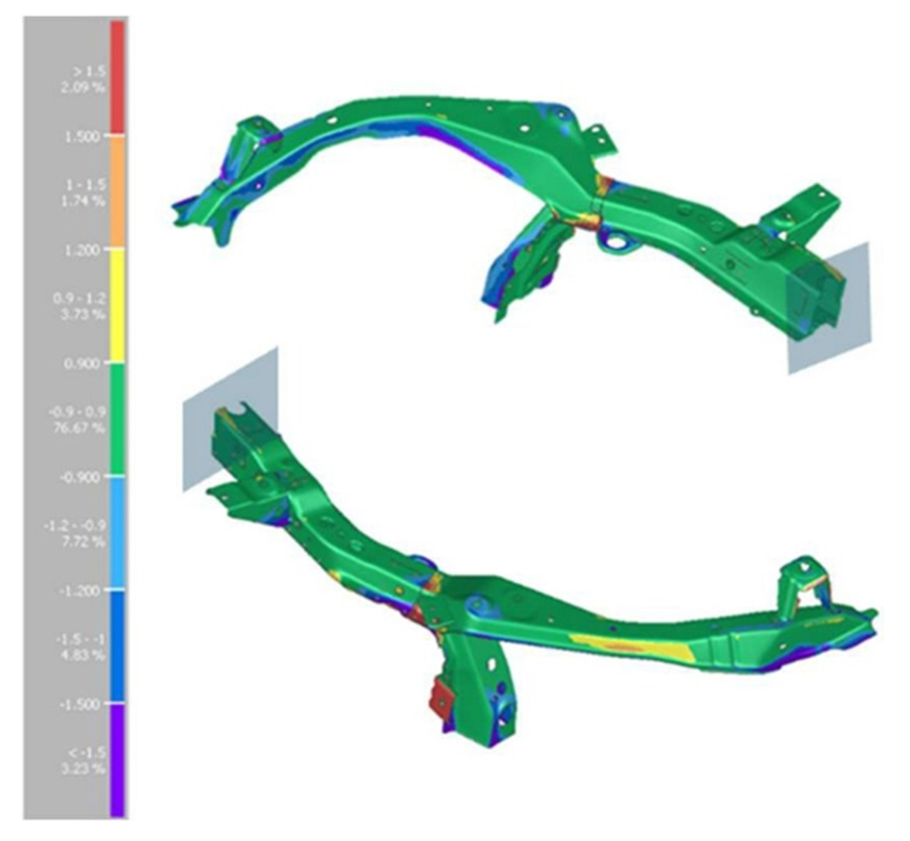
Figure 14. Dimensional deviations on the left side, based on the hybrid simulation (Use Cases 2, 3, and 4), in millimeters.
To achieve a stronger correlation, correlation, a higher level of input data would be required. Ensuring the traceability of the raw materials used in each component, along with information on the mechanical properties of each sheet, is essential. Thus, a common point can be established at this stage, and the try-outs can be performed fully digitally—adjusting, if necessary, the welding point sequence or the position of fixing points (clamps and pilots)—and progressively improving the assembly’s dimensional deviations.
The virtual assembly try-out fosters significant progress in reducing costs, scrap, losses, and production downtime, allowing correction loops to be completed entirely in a virtual environment and replicated only once the ideal positions have been identified. This approach supports greater integration between departments, making it possible to create analysis and correction scenarios while sharing information that feeds back into earlier stages. This aspect is more evident in Figure 16, which shows the possibility of correcting processes and interconnecting them retroactively according to the proposed flowchart. Moreover, it is possible to generate an optimal mathematical geometry, referred to as a VAR (Virtual Assembly Reference), which makes it possible to enhance the entire assembly through a stamping correction proposal. Using this approach, individual components are compensated so that, provided they meet their own specifications, the assembly specifications are also fulfilled.
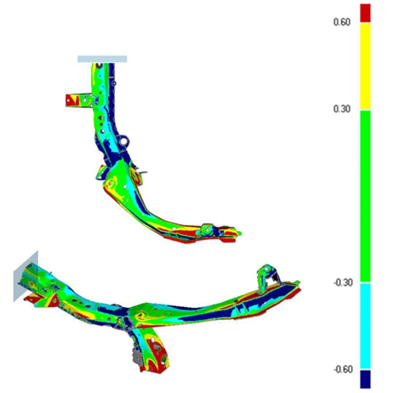
Figure 15. Real versus virtual correlation on the left side of the Front End Tie Bar.
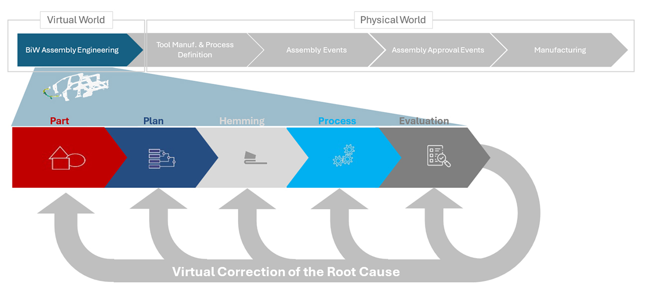
Figure 16. Virtual root cause correction through departmental integration.
CONCLUSION
The digital twin of the process enables corrections to the variations found in the assembly after the welding/hemming process by adjusting either the assembly device or, if necessary, the stamping tool, taking non-linear variations into account. This is possible because, by connecting the entire ecosystem—from raw material definition to product creation, stamping tool manufacturing, and BiW assembly—it becomes feasible to identify and prevent potential production failures, avoiding waste, enhancing productivity, and aligning with ESG policies (environmental, social, and governance), such as reducing pollutants.
In the study performed using CAD-0 for welding simulation, it was possible to identify the dimensional trend of the assembly imposed by the process. Analyzing the result of Use Case 1 (Figure 11), and considering the overall tolerance of ±0.9 mm, 77.76% of the dimensional area was approved, leaving only the ends of the part above 1.2 mm. It is important to stress that the input data at this stage were the geometry of the parts, raw material characteristics, thickness, and the support points and locations of the welding/measuring devices. Therefore, the conclusion is that Use Case 1—in the development phase—will be fundamental in defining support points (datums), welding spots, and the assembly sequence, with emphasis on dimensional stability and cost optimization for acquiring production and operational resources.
For Use Case 2 (Figure 12), in which the individual parts came from the forming simulation results—i.e., thinning, residual stress, and dimensional information for each item were computed and imported into the welding simulation—there was a marked increase in model accuracy. The influence of the stamped parts on the assembly’s dimensional trend was thus confirmed, resulting in a total approved area of 63.53%.
It was concluded that each stamped component, originating from the forming process, directly impacts the assembly regions—even if most are within their specified tolerance of ±0.6 mm. These deviations can affect the assembly region and generate gaps of up to 1.2 mm between adjoining parts when extreme tolerances coincide.
The results show that the central region of the assembly remained stable, except for two components at the bottom, which deviated more. Compared to CAD-0, this indicates that the assembly region of these components is critical, demanding stricter process control. The same applies to the side arms, which displayed larger dimensional deviations in the comparison.
In the final project phase, the dimensional correlation between the simulation and the real outcome was evaluated using the hybrid simulation (Use Cases 2, 3, and 4, Figure 14), combining the results from Use Case 2 with scanned data from individual formed parts. The total approved dimensional area was 76.67% for the left side of the assembly—a satisfactory result, though some points showed lower correlation with practical outcomes. Further efforts to improve correlation were not within the scope of this paper and will be examined in future work. Another possible approach involves performing robustness analyses on the individual formed parts, taking variations in raw material properties into account and observing the resulting dimensional impacts. These data could then be integrated into the assembly simulation, subjecting the assembly to an evaluation that includes the dimensional variability of the formed components.
The conclusion of this work is that, for a better representation of the digital twin of the process, the quality and detail of the input data are decisive for the accuracy of the model—particularly regarding support points, clamps, welding spot sequencing, assembly sequence, and part robustness. Beyond virtually identifying, for the first time, the welding process’s impact on assembly dimensions, the study also focused on correlating real-world and virtual processes. The robustness analysis of the individual parts was not considered, and the assembly that was scanned was not the same set of individual parts that were scanned, which can create discrepancies due to raw material property variations. The result was satisfactory for the study, although it was a reverse-engineering approach, and more time will be required in future projects to gather and input this information into the simulation. For new developments, the process steps have been defined following Use Cases 1 and 2. The robustness of individual parts, along with data on support points, clamps, locators, and spot welds obtained from the simulation, will be made available to the design, Tool Shop, Body Shop, and production teams to guide the construction of devices, thereby increasing accuracy throughout the process.
Authors:
João Roberto Ponse Júnior
Aleksandro Antônio Carmo
Osmar Luque Júnior
General Motors Brazil
Gustavo Luiz Silveira e Silva
Lucas Bertasso Mazieiro
Marcel Antônio Roxin Júnior
Aethra Automotive Systems
Luis Augusto Castilho Valdo
Wesley Aparecido da Silva
AutoForm Engineering
REFERENCES
- DE SOUZA, T.; ROLFE, B.F. Understanding robustness of springback in high strength steels. International Journal of Mechanical Sciences, v. 68, p. 236-245, 2013.
- CHEN, P.; KOC, M.; WENNER, M.L. Experimental
investigation of springback variation in forming of high strength steels. Journal of Manufacturing Science and Engineering, v. 130, 2008.
- GÖSLING, M.J. Metamodell unterstützte simulation und kompensation von rückfederungen in der blechumformung. Dissertation. Technische Universität Dortmund, 2010.
- TINTI, ; FONTANA, M.; SCINTILLA, L.D.;
MIRABILE, A.; CARLEER, B. Assembly simulation development and validation project with industrial applications. IOP Conference Series: Materials Science and Engineering, v. 1238, 2022.
- BÉZI, Z.; BAPTISZTA, B.; SZÁVAI, S. Simulation and
Validation of Welded Joints of High Strength Steel Sheets. 6th International Conference: Scientific Computing to Computational Engineering, 2014.
- PRÉM, L.; BÉZI, Z.; BALOGH, A. Development of
Complex Spot Welding Technologies for Automotive DP Steels with FEM Support. Vehicle and Automotive Engineering: Lecture Notes in Mechanical Engineering, p. 407-423, 2017.
- VALEŠ, M.; HAVELKA, J.; CHRÁŠŤANSKÝ, L.;
TATÍČEK, F.; NOVÁK, V. Production and assembly of car body fifth door with use of dual-phase steel hct500x. IOP Conference Series: Materials Science and Engineering, v. 1178, 2021.
- SCHULER, F.; LIEWALD, M.; BEZERRA, D.M. New
compensation strategy for car bonnet assemblies. Procedia Manufacturing, v. 29, p. 552-559, 2019.
- DONDERS, S.; BRUGHMANS, M.; HERMANS, L.;
TZANNETAKIS, N. The Effect of Spot Weld Failure on Dynamic Vehicle Performance. Sound and Vibration, p. 16- 24, 2005.
- JESSOP, BOB. Fordism. Encyclopedia Britannica, 2020. Available at:
<https://www.britannica.com/money/Fordism> Accessed on May 09, 2024.
- AMTHIOU, HANAN & ARIOUA, MOUNIR & BENBARRAD, TAJEDDINE. (2023). Digital Twins in
Industry 4.0: A Literature Review. ITM Web of Conferences, v. 52, 2023.
- SONG, Q.; ZHANG, W.; BAY, N. An Experimental
Study Determines the Electrical Contact Resistance in Resistance Welding. Welding Journal, USA, v. 84, n.5, p. 73-76, 2005.
- RESISTANCE WELDING MANUAL. 4 ed. rev.,
RWMA, Philadelphia, 2003.
- ASLANLAR, S. The Effect of Nucleus Size on Mechanical Properties in Electrical Resistance Spot Welding of Sheets Used in Automotive Industry, Materials and Design, v. 27, p. 125-131, 2006.